Russellc, based on my problem description, do you think that is my problem? i.e. mosfets?For what its worth, B & D still has a bunch of these, I just ordered a few pairs.
Russellc
If you use the Fairchild devices, you must use 1k trim pots - like 6L6 said. There is a explanation for it in the build guide I think..
Thanks, I did in fact use Fairchild. I obviously missed that 1K requirement. 1K pots on order! Thanks again.If you use the Fairchild devices, you must use 1k trim pots - like 6L6 said. There is a explanation for it in the build guide I think..
Just get the suggested pots. I hadn't checked the Fairchild's way cheaper price! 7 bucks vs 88 cents!
Russellc
Russellc
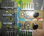
PSU rails
Is there an optimal voltage for the BA-3 as a preamp? Is +/- 24V 'fine' without component adjustments?
Thanks,
Ryan
Is there an optimal voltage for the BA-3 as a preamp? Is +/- 24V 'fine' without component adjustments?
Thanks,
Ryan
Is there an optimal voltage for the BA-3 as a preamp? Is +/- 24V 'fine' without component adjustments?
Thanks,
Ryan
Likely anything close is good, I used 22+22 volt 50 VA Antek, just because I had them. If you use something that is going to make over 25 volts, you may want to use 35 volt 1000uF caps instead of 25 volt. Most are conservative enough it isnt a problem, but I upped mine to 35 volt. They were ordered at the same time I increased them on my BA-3 Power Amp build, which did have rails above 30 volts, so again I had them on hand.
I think 6L6's BA-3 preamp build used 20 + 20, but Antek was out, so I got a couple of the 22 + 22 volt jobs. Beyond 35 volts your J fets are sort of in danger area unless you cascode. No provision on board so you would have to cobble the cascode on....I dont think it is worthwhile....no one else seems to have done it anyway, to the preamp.
Russellc
Last edited:
+/- 24V is what the circuit was designed around, but it also works beautifully at 32v. A couple volts either way from 24 makes no difference, so if you are in the general ballpark, go for it.
As Russell says, more than that and your Jfets become imperiled.
Check your PM.
As Russell says, more than that and your Jfets become imperiled.
Check your PM.
Optimum pot value for BA-3 pre
What is the optimum pot value to use for the BA-3 pre? And any comments about type such as series, shunt or ladder, etc?
Thanks. Nash
What is the optimum pot value to use for the BA-3 pre? And any comments about type such as series, shunt or ladder, etc?
Thanks. Nash
What is the optimum pot value to use for the BA-3 pre? And any comments about type such as series, shunt or ladder, etc?
Thanks. Nash
Ok just found the thread on attenuators for Pass pre's. Decided to go with a 10k stepped attenuator.
Trying ZenMods suggestion of Silmic and mkc as an output cap which sounds pretty good so far.
[/QUOTE]
Marra, Zen Mod could you please elaborate on the MKC. What value, brand?
I know this was discussed a while back but I cannot find it.
Thanks. Nash
[/QUOTE]
Marra, Zen Mod could you please elaborate on the MKC. What value, brand?
I know this was discussed a while back but I cannot find it.
Thanks. Nash
I think MKC means metalised polycarbonate.
They stopped making capacitor polycarbonate film quite a few years ago.
VERY few capacitor manufacturers use polycarbonate now and they tend to be very expensive.
MKP is usually better for all duties. That may be why they stopped carbonate, it had nothing to offer in the capacitor winding market that other materials could not offer.
MKT and MKP stand either side of MKC.
Firing up my third BA-3 FE and first one to give trouble....
It uses Toshiba Mosfets from B & D that 6L6 told us about, dont know if it is them or something else.
Problem is, unlike the first two, I cant get past .750 across R10 & R11 while turning P1 and P2 COLLECTIVELY...by this I mean I can turn one up to 1.0 across R10 & 11, but when you attempt to bring the other one up, the other comes down.
With my first two, you could just keep edging up...Even though they are the Toshiba mosfets, perhaps I need to go to the 1000 ohm pots...or change out mosfets with a set of the remaining two amps worth that I was saving for a pair of BBA-3 mono blocks. Those sets came from member Prakit which I used in the other two builds. Worked great in other two...
Second problem, which makes me wonder if I am getting tired and miss wired something, is that there is 22.7 volts of DC, and it does not change as P1 and P2 are adjusted. This is the same on both sides, measured from R12 to ground or from the top of the Cap to ground.
I'm staring at one of my working ones looking for a wiring error, but may need to wait until tomorrow to look clearly.
Any Ideas of where I slipped up? Or where a defective part could be? I reread the thread, especially Delacoys adventures, but I am just not seeing it tonight, yet.
Thanks in advance,
Russellc
Last edited:
Just caught it. Noticed one of the 1000uf caps ends was slightly "ballooned."
All of them are oriented correctly but holy dumb bunny power supply wiring
blunders. Hopefully didnt cook any thing fet wise or Mosfet wise. I have another set from B & D. Really want to save what I know are good and from same source for BBA-3 mono blocks. Also have more J fets, really dont want to waste those
On my last two, there were separate wires going from power supply to board.
On this build, I put a terminal block in between so I could easily undo the V+, V-, and the ground wires. Getting tired, and getting in a hurry, I wired the V+ and V- on each side TOGETHER to the same leg.
Fortunately I was using a variac and am hoping that one cap with slightly swelled end is all the damage, too many distractions and dumb mistake made.
Live and learn,
Russellc
Oh well, looks like damage done. Rewired, turning pot to minimum, P3 remaining in mid position and fired up with variac, up just over 1.0 volt across R11 and R12 at just 40 volts of 120 mains here.
At least the power supply points all measure correctly.
Will replace mosfets tomorrow and retry, if that doesnt do it I guess it got the J fets as well. That's all I can tear up tonight.
Russellc
At least the power supply points all measure correctly.
Will replace mosfets tomorrow and retry, if that doesnt do it I guess it got the J fets as well. That's all I can tear up tonight.
Russellc
This is where the Mains Bulb Tester comes into it's own. It lights up when you try to power ON with a wiring error.
But there is a further modification you can do to make your amplifier closer to bullet proof.
Add a 1n4002, or higher, across each of the main supply rail decoupling capacitors. This shorts a mis-wired power input turning on the filament and ensures a reverse voltage never exceeds 1Vdc
But there is a further modification you can do to make your amplifier closer to bullet proof.
Add a 1n4002, or higher, across each of the main supply rail decoupling capacitors. This shorts a mis-wired power input turning on the filament and ensures a reverse voltage never exceeds 1Vdc
Yes, just got a little over confident and in a hurry and made a careless mistake. I have a dimbulb setup, but didn't think I needed it. Bad decision.
Live and learn. Getting ready to change mosfets...then likely the Jfets too.
Russellc
Live and learn. Getting ready to change mosfets...then likely the Jfets too.
Russellc
- Home
- Amplifiers
- Pass Labs
- The BA-3 as preamp build guide