Super reg does not include rectifiers or filter caps on pcb. So take that into consideration.
Sounds great though.
Sounds great though.
I’m building a BA3 preamp and could use some help with my build as I’m still a novice. I bought a Kubota Full Blown Regulator. First question I have is:
- should the voltage be +-24 across V+ and V- or should I read 24V across each side? I’m only getting between 12.5V and 14V across each side and between 24 and 26V across both sides. Is this correct?
-Also, what is the process for setting each trimmer? Both are multi turn and I’m struggling to get them to move consistently. Do I turn one side at a time or turn them together?
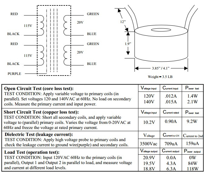
I’m using an AS-1220 transformer.
- should the voltage be +-24 across V+ and V- or should I read 24V across each side? I’m only getting between 12.5V and 14V across each side and between 24 and 26V across both sides. Is this correct?
-Also, what is the process for setting each trimmer? Both are multi turn and I’m struggling to get them to move consistently. Do I turn one side at a time or turn them together?
I’m using an AS-1220 transformer.
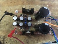
Attachments
+24v from V+ to GND, -24v from V- to GND.
Do you have a link to your PSU board? (or better, a schematic?)
The process for bias is identical to the F5 - you start increasing the bias on both pots equally until they start to read something, then you increase it a little, then null the offset to 0, which will take a little bias away, increase it more, null the offset again, until you have it as desired. It really helps to have the input shorted and a 5-10 k resistor on the output, to give the circuit something to look at when its being set.
Last edited:
give more info about Kubota - what range of voltages your set is declared to have
also , put proper info about xformer here , don't let us crawl around for datasheet
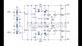
you need to connect to input AC1 , CT , AC2 ......... practically 40Vac having center tap ( I crawled around for your xformer ; so Green1 is AC1 ,Blue1 tied with Green2 are CT , Blue2 is AC2 ; count them from top of picture )
on output you need to have +24Vdc, GND , -24Vdc
also , put proper info about xformer here , don't let us crawl around for datasheet
you need to connect to input AC1 , CT , AC2 ......... practically 40Vac having center tap ( I crawled around for your xformer ; so Green1 is AC1 ,Blue1 tied with Green2 are CT , Blue2 is AC2 ; count them from top of picture )
on output you need to have +24Vdc, GND , -24Vdc
Sorry. I should have been more clear. I’m only testing the regulator to ensure it works properly before testing it on the BA3 board. I’m not able to get past 14V on each side and turning the trim pots doesn’t seem to do much. I’ve emailed the seller for clarification.
Below is a link to the Kubota. I currently don’t have another copy of the schematic. That is all the seller sent me.
Kubota low noise regulator full blown version kit https://www.amazon.com/dp/B01F8U9AIE/ref=cm_sw_r_cp_api_i_eE.JDbX48MGG6
Below is a link to the Kubota. I currently don’t have another copy of the schematic. That is all the seller sent me.
Kubota low noise regulator full blown version kit https://www.amazon.com/dp/B01F8U9AIE/ref=cm_sw_r_cp_api_i_eE.JDbX48MGG6
Ok, interesting reg, looks like it might work nicely.
But you need the schematic so we can try to figure it out.
EDIT : Ah, you addd the schematic to your above post. Do what ZM says.
But you need the schematic so we can try to figure it out.
EDIT : Ah, you addd the schematic to your above post. Do what ZM says.
Last edited:
just connect everything as I wrote , then turn pot ( one by one , rails are independent) to read max voltage and inform here
if you can get both rails to 24V (one positive , second negative) then you're good
if you can get both rails to 24V (one positive , second negative) then you're good
Ok, interesting reg, looks like it might work nicely.
But you need the schematic so we can try to figure it out.
reg is basic and crude
pcb is so-so , but I can bet that phase characteristic isn't ideal ..... no base and gate resistors , no compensation cap on sense side , no degeneration in LTP
but , chances are that it'll not whistle , at least 🙂
Yea. Looks like I just need to swap two of the wires so green 1 is tied to green 2 on AC1. I’ll give that a try. I mainly went with this regulator as I saw it was one used by another member and I had Amazon points to fund it so it was free. I bought a super regulator board to upgrade to later.
Just going by the maximum and minimum input and output specs it doesn't look like there is much voltage drop across the regulators. If the specs mean 33V input gets you 45V output, then there is only a ~1.5V drop across the regulators. If my thinking is correct, than you should be able to produce 26.5V with your 20V transformer.
100VA xformer , still small enough to have lesser regulation , should have little higher AC voltage with light load
so , we can expect little more than 20 x 1.41 , as usual for lightly loaded rectifier/filter combo
so , we can expect little more than 20 x 1.41 , as usual for lightly loaded rectifier/filter combo
Zen Mods wiring is what the unit needed. I just had to connect the center tap and I have enough voltage on V- and V+.
As I adjust one side it pulls from the other so it’s tricky getting them even. I’m easily able to get around 26V minimum on each side but no lower. Is this ok for the BA3?
Thanks again for the help.
As I adjust one side it pulls from the other so it’s tricky getting them even. I’m easily able to get around 26V minimum on each side but no lower. Is this ok for the BA3?
Thanks again for the help.
that reg isn't working properly, at least for your needs and available input voltage
any chance to decipher schmtc , so we can change what's needed
any chance to decipher schmtc , so we can change what's needed
Quick update. I found out the two regulators were swapped so I fixed my error, but having issues getting both sides up to 24V. One side is fine as the other won’t adjust high enough.
I checked the voltages after the bridge at the large caps and I’m getting 33V on one side and 22V on the other. I fear I may have damaged a component when I first hooked up the power supply incorrectly or from reversing the regulators. I’m going to start by checking the diodes
I’ve requested a better schematic from the seller.
48v @ 110 ma = 5.5w
25VA 24vac CT transformer = 38v each side no load 36v - 35v under load
76v @ 120ma = 9.12w total load (regulators draw a small amount. plus losses)
transformer voltage is at rated load.
24v regulator will work perfectly.
25VA 24vac CT transformer = 38v each side no load 36v - 35v under load
76v @ 120ma = 9.12w total load (regulators draw a small amount. plus losses)
transformer voltage is at rated load.
24v regulator will work perfectly.
Last edited:
After some measurements today, I am now getting 28V on the V+ side and 26V on the V- side after the bridge rectifier.
I am able to adjust V+ to a perfect 24V but the V- will only adjust to 22.5V. Would this be ok to run the BA3 or does each side need to be perfect?
I am still waiting on the seller to replay with schematic.
I am able to adjust V+ to a perfect 24V but the V- will only adjust to 22.5V. Would this be ok to run the BA3 or does each side need to be perfect?
I am still waiting on the seller to replay with schematic.
- Home
- Amplifiers
- Pass Labs
- The BA-3 as preamp build guide