Thanks for the quick reply.
I did . Measured at the caps positive and negative terminals with ohm meter to zero . Turning the p1 and p 2 seems to have no effect. I double checked the pots to make sure they are not defective.
I did . Measured at the caps positive and negative terminals with ohm meter to zero . Turning the p1 and p 2 seems to have no effect. I double checked the pots to make sure they are not defective.
No, Q3= FQP3P20
Q4= FQP3N30
This is from the BOM
Burning Amplifier Gain Stage for BA-3 – diyAudio Store
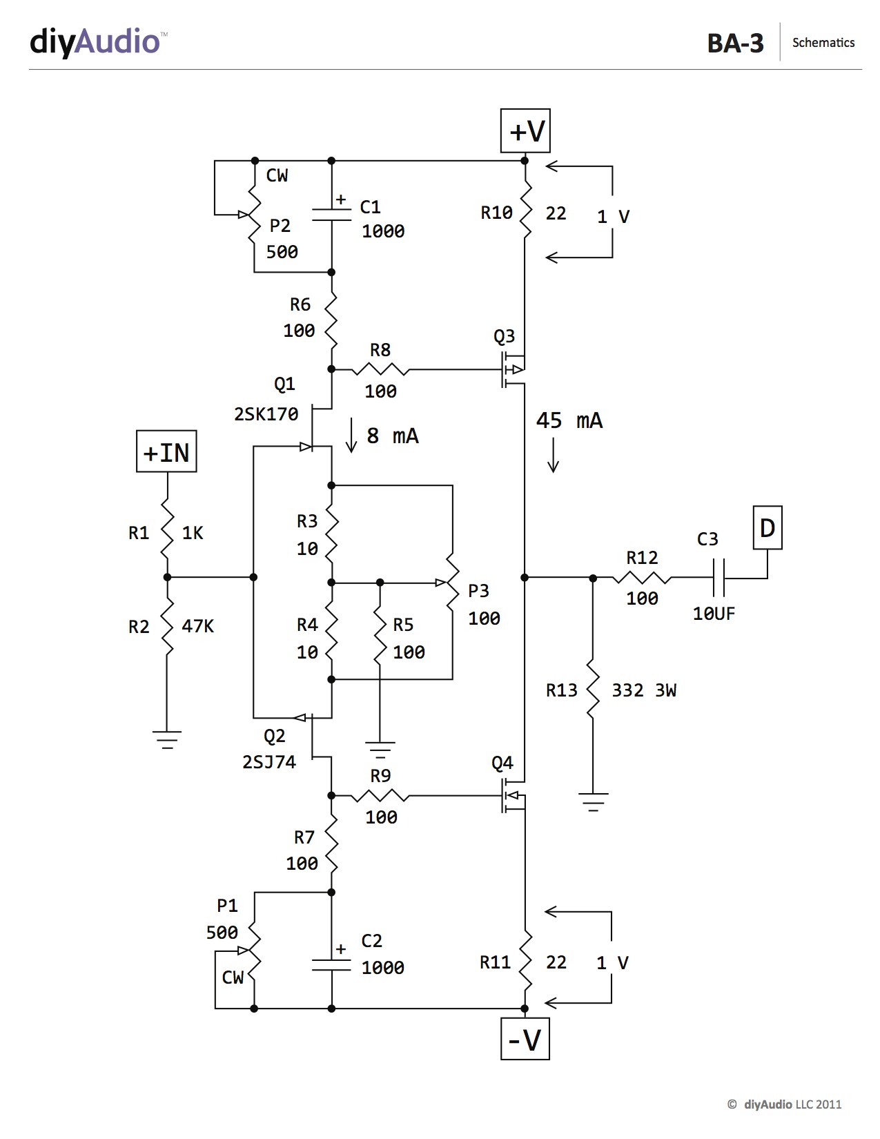
Also if you look at the schematic you will see that Q3 is the P and Q4 is the N
Q4= FQP3N30
This is from the BOM
Burning Amplifier Gain Stage for BA-3 – diyAudio Store
Also if you look at the schematic you will see that Q3 is the P and Q4 is the N
Last edited:

The four devices in the DIYaudio sch attached to post606 are all FETs.
It would be nice if DIYaudio could append Nch and Pch to the relevant devices.
It would help Builder Members to get this right first time.
In addition the mosFET symbols are not correct. The arrow direction and the double bond to the Source are correctly shown, but the shape of the gate connection should look like the lower diagram supplied by 6L6.
Ask DIYaudio to correct the schematic and think about incorporating the N/P information.
Great ideas all, Andrew. 😀
The Mosfet were unlabeled as there are multiple devices that could work, 2SK2013/2SJ313, IRF 601/9610. Fairchild FQP3N30/FQP3P20.
Please make the changes you see fit and I'll happily integrate the new drawings into the documentation.
The Mosfet were unlabeled as there are multiple devices that could work, 2SK2013/2SJ313, IRF 601/9610. Fairchild FQP3N30/FQP3P20.
Please make the changes you see fit and I'll happily integrate the new drawings into the documentation.

Success gentleman.
Swapped the mosfets as suggested above.
Biased to 0.95v with stable .5 to 1 mv offset. Will leave there for now as suggested by 6l6 in his build guide and tweak final settings when she is settled in a case with lid on.
Will complete the other channel as well today and wants to see how the preamp sounds.
Thanks again for all the help🙂
Hi Andrew,
I followed the schematic and made the error as explained.
Your suggestion should prevent errors in future builds. Fortunately I used all precautions with a variac and discovered something was wrong before it fried the precious Jfets.
I followed the schematic and made the error as explained.
Your suggestion should prevent errors in future builds. Fortunately I used all precautions with a variac and discovered something was wrong before it fried the precious Jfets.
Don't use a Variac. Your reaction to something being amiss is too slow.
Use a Mains Bulb Tester. It is automatic, it is on the cusp of being unstable and just needs a bit more prolonged current and the bulb glows bright, leaving a tiny voltage at the output of the secondary/s
You will need a very low wattage bulb for the very low consumption of the pre.
Use a Mains Bulb Tester. It is automatic, it is on the cusp of being unstable and just needs a bit more prolonged current and the bulb glows bright, leaving a tiny voltage at the output of the secondary/s
You will need a very low wattage bulb for the very low consumption of the pre.
Re: Misplaced Mosfets
When I read the recent postings, they concerned me, as I had built a stand-alone BA-3 and wondered if I also might have misplaced the Mosfets, even though I had not experienced any problems as described. But after going back to Mr. Pass' BA-3 article, I was able to put my mind at rest.
The schematic in Mr. Pass' BA-3 article has them correctly, see:
<<http://www.diyaudio.com/forums/diyaudio-com-articles/194809-burning-amplifier-ba-3-a.htm>>
Also, Mr. Pass indicates in the BA-3 article that the BA-3 front end "is a relative of the F5 amplifier, scaled down and absent the feed-back loop." The F5 has the source of the P channel Mosfet attached to positive DC and the source of the N channel Mosfet attached to negative DC.
As Zen Mod often reminds us, we can benefit greatly by reading Papa's articles to better understand what we are building.
In this case, the reversed Mosfets appear to be an artifact of the schematic published in connection with the Diyaudio Store page.
if you don't mind slightly more complicated , you can build either Shunty or Good Gemini regs
schmtcs are open source
schmtcs are open source
if you don't mind slightly more complicated , you can build either Shunty or Good Gemini regs
schmtcs are open source
aaaaaaa man 🙂
now I have to check out pumpkin too... 🙂
Gemini you mean this one?
http://www.diyaudio.com/forums/blogs/rjm/1120-voltage-regulators-line-level-audio-geminips.html
This looks a bit less intimidating...
Last edited:
The funny thing is that I read about it both on that thread and on your blog, but for some reason it did not register properly on my brain... I need more sleep...
Sent from my HUAWEI NXT-L29 using Tapatalk
Sent from my HUAWEI NXT-L29 using Tapatalk
Hi guys,
I'm experiencing a strange problem with my BA3 preamp build. Everything sounds and seems fine until I turn up the volume to a loud level, then one channel fades out and stops working. When I turn the volume back to a lower level the channel "returns". The volume level when the channel cuts out isn't excessive, just a normal loud listening level. The sound is very clear and detailed with no hint of distortion otherwise. I was able to bias things properly and have less than 10 mv offset on both channels. Tore out the original pot and input switch that I had in hopes that could be the issue, replaced with a new 50k pot, and no input switching, just a single input to simplify things, still getting same problem. I have a robust psu, and checked voltages while running before and after channel cuts out, rock steady 24v, no sagging. I triple checked the component values and they all comply with the bom. My final act will be to reflow all of the solder joints. At this point I'm scratching my head as to what could be causing this issue. Does anybody have any ideas, or advice.
Thanks,
Paul
Normal troubleshooting questions -
The problem stays the same if you switch the input wires L to R?
The problem follows the output if you switch the output wires L to R?
Have you measured the bias voltages when the channel drops out?
Please post some well-lit, in-focus photos. I am always amazed at what some members can see.
The problem stays the same if you switch the input wires L to R?
The problem follows the output if you switch the output wires L to R?
Have you measured the bias voltages when the channel drops out?
Please post some well-lit, in-focus photos. I am always amazed at what some members can see.
- Home
- Amplifiers
- Pass Labs
- The BA-3 as preamp build guide