Small delay...but don't have progress here
Maybe some can look over it.
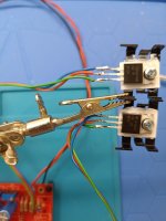
This is my second PCB. M first try es with recommended Toshibas now I change to Fairchild (2k trimmers for P1,P2)
 and check the JFets. For my I don't get it now.....but I have a lot of Hifi gear here, so I'm not blocked for my sound sessions..


Maybe some can look over it.
This is my second PCB. M first try es with recommended Toshibas now I change to Fairchild (2k trimmers for P1,P2)
Attachments
@DIYHarry -
This is more a question for others and a learning chance for me... So, apologies if this is completely irrelevant. Maybe, I'll get lucky...
Is this a case where the flywires have maybe put too much 'distance' between the MOSFETs and the source and/or gate stopper resistors?
I've seen that mentioned in a few situations. Typically that's for MOSFETs for power amp output stages though. I fully, 100% admit that I don't know if that's the situation here. I also have no idea if that's how that problem manifests itself as a symptom or if it even applies.

it happend first with implemented Toshibas ON board.
I suspect at first the error was due to the MOSFET and wired the fairchild extern to change different MOSFETS.
So errors happen in a normal stage of building with correct implemented MOSFET first.

I suspect at first the error was due to the MOSFET and wired the fairchild extern to change different MOSFETS.
So errors happen in a normal stage of building with correct implemented MOSFET first.
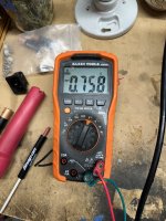
if I measure GND do Drain of JFETS (ch1yellow; blue is output)---voltage increase with lower frequencies.
This is what I dont understand by now. (...reactance C1,C2....or what?????)


This is what I dont understand by now. (...reactance C1,C2....or what?????)
Only try to find and understand why and where is the freq. dependency.
I was so paranoid that I also resolder the blue nichicon's C1,C2 and check them. They are ok.
Have no idea..project on hold....
Make my own KiCAD file with some snubber in rails etc ..will see
I was so paranoid that I also resolder the blue nichicon's C1,C2 and check them. They are ok.
Have no idea..project on hold....
Make my own KiCAD file with some snubber in rails etc ..will see
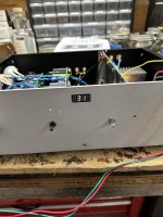
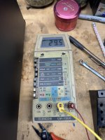
Off topic maybe, are there any opinions on that particular scope? Seems to have good reveiws and price. Been watching forum pics for scopes to buy for years.testing with scope?
Danke, H.
What can you tell me about those input cable/wire.
I have what looks the same I bought from salvage
store many years ago and never knew what they
are. The center conductor on mine look to be
a white Teflon insulator.
Thanks

I have what looks the same I bought from salvage
store many years ago and never knew what they
are. The center conductor on mine look to be
a white Teflon insulator.
Thanks
Thanks!
Mil-Spec Coax, 50 Ohm, RG-178, 30 AWG (7x38) Silvered Copper Covered Steel Conductor,
PTFE Insulation, 95% Silvered Copper Braid Shield, FEP Jacket,
Commercial, non-QPL
I wonder if I should be concerned about the steel conductor? Maybe it
doesn,t matter as perhaps an audio signal passes on the outer skin
which is silver copper?
https://catalog.belden.com/techdata/EN/83265_techdata.pdf
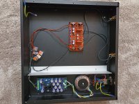
it was not the measurement.....it was the desk power supply cabling.... I fix this on Wednesday and finally I got a confirmation from stuartmp with his video https://www.diyaudio.com/community/...he-wolverine-build-thread.385920/post-7515968care to explain methodology of your testing with scope?
so to all...DO NOT wire GND-PE with your floating supply...for some reasons I overlook this topic....past erros apear due a ground loop from supply-wave generator- and scope----I knew it...put dont look there...🙄
please see correct calbing below..
Last edited:
This scope is very ok, but there a lot of others.Off topic maybe, are there any opinions on that particular scope? Seems to have good reveiws and price. Been watching forum pics for scopes to buy for years.
Danke, H.
I can recommend YT kiss Analog, he also show e.g. micsig scopes
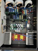
Flawless function with both BA-3
First is with Glassware 18 V ( will change this for higher V)
2nd is with Mark Johnson 20V and Toshibas 😁🥹
Both reduced to 13.5dB
Oh men, I'm happy

First is with Glassware 18 V ( will change this for higher V)
2nd is with Mark Johnson 20V and Toshibas 😁🥹
Both reduced to 13.5dB
Oh men, I'm happy
Attachments
Last edited:

- Home
- Amplifiers
- Pass Labs
- The BA-3 as preamp build guide