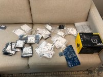
The LGA1567 heats sinks I ordered arrived today.
They seem a bit small, measuring about 3.75" (95mm) across.
Are we sure these are big enough?
I use a sink about 1.5x that in my computer.
Thanks,
-Josh
They seem a bit small, measuring about 3.75" (95mm) across.
Are we sure these are big enough?
I use a sink about 1.5x that in my computer.
Thanks,
-Josh
The LGA1567 heats sinks I ordered arrived today.
They seem a bit small, measuring about 3.75" (95mm) across.
Are we sure these are big enough?
I use a sink about 1.5x that in my computer.
Thanks,
-Josh
Hi Josh,
If using an OEM solution, the Dell FD841 heatsinks are most used.
I’m not familiar with the heat sinks you purchased??
DELL FD841 HEATSINK PRECISION ACCESSORIES Search Page.
My BOM
It's my favorite day of the week: BOM delivery day! I went largely with Vunce's Mouser BOM, plus my corrections. For the DC coupling caps I am going to do MKP1840s (QTY (3) MKP1840 10uf 160V 10% METALLIZED POLYPROPYLENE BOX FILM MKP1840610165 | eBay), they should fit nicely. I have a pair of 32v/600va Antek's enroute as well, figured I would oversize them since I should have the space.
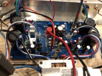
For thermals I am going to attempt the water cooling route with 2x Corsair H60s per channel (https://www.corsair.com/us/en/Categ...2018)-120mm-Liquid-CPU-Cooler/p/CW-9060036-WW). I ordered one from Amazon for $70 to test fit (both mechanically and electrically) and noodle on before ordering the rest.
Not sure when I'll get to actual construction, Loafimus is going to kill me if I don't finish up an IcePower 500ASP monoblock build we've been working on, but I'm super excited for how this one is going to come together 😀
Thanks all for your hard work, let me know if there is anything I can help with to assist others building the ABBB.
Greg
It's my favorite day of the week: BOM delivery day! I went largely with Vunce's Mouser BOM, plus my corrections. For the DC coupling caps I am going to do MKP1840s (QTY (3) MKP1840 10uf 160V 10% METALLIZED POLYPROPYLENE BOX FILM MKP1840610165 | eBay), they should fit nicely. I have a pair of 32v/600va Antek's enroute as well, figured I would oversize them since I should have the space.
For thermals I am going to attempt the water cooling route with 2x Corsair H60s per channel (https://www.corsair.com/us/en/Categ...2018)-120mm-Liquid-CPU-Cooler/p/CW-9060036-WW). I ordered one from Amazon for $70 to test fit (both mechanically and electrically) and noodle on before ordering the rest.
Not sure when I'll get to actual construction, Loafimus is going to kill me if I don't finish up an IcePower 500ASP monoblock build we've been working on, but I'm super excited for how this one is going to come together 😀
Thanks all for your hard work, let me know if there is anything I can help with to assist others building the ABBB.
Greg
Attachments

BOM UPDATE increase R308 to 150K
In order to extend the SSR delay time, R308 needs to be increased to 150K.
This gives approximately 6seconds from power up for the ABBB to settle before signal is passed to the speaker. This ensures no thumps are heard or DC surge gets to the speakers when powered up.
MBA02040C1503FC100 Vishay / Beyschlag | Mouser
Attachments
Exciting times, Gtose! Have fun and good luck with the build!
Thanks for the tip on extending the startup delay, Vunce! The stock value is 3 seconds but I guess that wasn’t long enough for the amp to settle.
Thanks for the tip on extending the startup delay, Vunce! The stock value is 3 seconds but I guess that wasn’t long enough for the amp to settle.
Hi all,
I went over all three schematics, the boards, the original BOM, and the Mouser cart with a fine tooth comb.
On top of the errata found by gtose, I found some errors in the terminals and headers.
I created a new spreadsheet from the Original BOM and the Mouser cart.
The new spreadsheet lists each part individually with their approximate locations on the boards, and which schematic they belong to.
The parts with alternate numbers are highlighted in different colors so they can be picked out more easily.
I added a tab with notes listing the changes.
The spreadsheet has the alternate numbers suggested by gtose, and R308 has been changed to 150K from 100K
I made some changes to the headers:
The terminals for the power supply are now tin 16awg instead of 18-24awg.
The terminals and headers for the audio circuit are gold 18-24awg
The input KK header is now gold 22-30awg, and I included terminals and the mating part.
A note of caution, do not mix tin and gold in connectors.
I scanned the boards, and added the pin numbers to all the headers, and the Rxxx and Cxxx numbers to the flying boards. Please ignore all the boxes drawn around the parts, it is the same image I used when mapping out the boards.
please feel free to put the attached .zip into the 1st post so folks can find it easily.
This was a boatload of work, but nothing compared to putting this project together. I want to thank you all again for all your hard work, cleaning up a list of parts is easy compared to putting it all together in the first place.
-Josh
P.S. total cost with my changes was $177.93 per channel + shipping, so the gold headers added about $12.00/channel - less than the cost of a single Noctua fan 🙂
Attachments
joshua43214, awesome, thanks for the consolidated BOM spreadsheet and extra set of eyes on the Mouser BOM. Good luck with your build!
With parts in hand, one issue I have identified so far is the lead spacing (2.5mm) on 810-FG18C0G1H470JNT0 (C215,235) is too small for the TH pads, though they could likely be bent to fit. I'll probably order 1206 SMD as a replacement (C1206C470J5GACAUTO KEMET | Mouser).
Also missing, if you want to use them as I see the current builds have them, are DIP 8 sockets for N221, N201, N301. I will probably go with 110-47-308-41-001000 Mill-Max | Mouser for these.
One remaining question I have (ha, as if it'll be the last) is that C302 (220uF/35V) is marked as non-populated in the BOM and I could not locate it in the schematic. However, I see this populated in Vunce's build. What's the consensus? Leave it in or omit? What purpose does it serve?
Greg
One remaining question I have (ha, as if it'll be the last) is that C302 (220uF/35V) is marked as non-populated in the BOM and I could not locate it in the schematic. However, I see this populated in Vunce's build. What's the consensus? Leave it in or omit? What purpose does it serve?
Greg
Hi Greg,
C302 is Non-Polar, Definitely not optional🙂
It’s part of the SSR Protection circuit.
https://www.mouser.com/ProductDetail/Nichicon/UVP1V221MHD?qs=61YFXr/enS4gn0f6vju3eQ==
C302 is Non-Polar, Definitely not optional
I must have conflated this with the "NP" used for various resistors in the BOM for resistor spaces that are non-populated (R148, R155).
That said, the BOM does specify the component as "POLARIZED CAPACITOR, European symbol" and on the silk screen, it is shown polarized w/ the positive pin marked, so not many hints are given that this is indeed used and non-polarized. Again, I could not find this in the schematic, though I might have glossed over it.
Looking again, it appears that maybe the schematic for the DC protect circuit was never published, I can't locate any of the components in the schematics in post #1.
Looking again, it appears that maybe the schematic for the DC protect circuit was never published, I can't locate any of the components in the schematics in post #1.
Post https://www.diyaudio.com/forums/gro...ttah-abbb-52w-class-amp-gb-3.html#post5822269 has it =)
The DC protection circuit was posted by x in post #26, and the initial BOM posted in post #132.
All three schematics (amp, power supply, DC protection) are marked as "preliminary." The only significant change I could find was the elimination of R148 and R155 (both marked NP in schematic). I also found the "NP" marking odd and stopped paying attention to that column of the BOM since the package info was more useful.
very good suggestion for the dip-8 sockets. I have some on hand and forgot to add them to the BOM.
C302 is a "can" style non-polar cap. I assume this is why the polarized symbol was used. My understanding is that these caps should be wired like a polarized cap (short lead to neg) for best results.
Sorry, I didn't measure the lead spacings, I took a quick look at the data sheet for C215/C235, they show a number for one with a wider lead spacing. I would probably just bend the leads out to fit - I ordered the SMD parts for my build.
I expect to build the amp in the spring. I wanted to make sure I had all the parts and infos right now so I would not have to re-read all the threads on this when I start on it. I really want to build it with round heat sinks on a copper sheet like an old school tube amp. Having trouble sourcing round sinks that are not stupidly expensive. It's very tempting to try and fab my own...
-Josh
Joshua43214,
Thanks for putting all of this info together! I will out a link you your compilation on Post #1.
X
Thanks for putting all of this info together! I will out a link you your compilation on Post #1.
X
I'm travelling at the momnt and hoping my PCB's will be at the P.O. when I return tomorrow.
In the meantime, can someone advise me as to what changes would be necessary to use 4 Ohm speakers (Magnepans)?
Thanks
Andrew
In the meantime, can someone advise me as to what changes would be necessary to use 4 Ohm speakers (Magnepans)?
Thanks
Andrew
PCBs arrived a week or so ago, thought i'd also chime in 🙂
look great and thanks to all for the BOM work. hoping to do start in the Spring. looking forward to it!
cheers,
Scott
look great and thanks to all for the BOM work. hoping to do start in the Spring. looking forward to it!
cheers,
Scott
Andrew,
Good to see you will building the BB. I think you will like it!
Have you been affected badly by Dorian? I hope not........
Hugh
Good to see you will building the BB. I think you will like it!
Have you been affected badly by Dorian? I hope not........
Hugh
Hi Hugh,
Its been awhile. I hope all is well.
Yes, I have decided to try the BB although the current plan is hopefully to use it with Magnepans which are a 4 ohm load. If not then so be it, I have other suitable speakers but I do enjoy the Maggies.
I have never heard SS class A so it will be all new to me.
Thankfully we escaped Dorian but my heart goes out to those that did not, particularly the Northern Bahamas.
I still have my original AKSA. I have not used it in awhile. I "borrowed" the transformers and never put them back in. One of these days I'll have to fire it up again.
All the best.
Andrew
Andrewbee, regarding settings for 4ohm operation, I will leave that to Hugh to answer. In general, the bias current needs to be boosted and if the heatsinks can handle the extra thermal load, then it’s fine. But oftentimes, voltage rails may be reduced somewhat to keep heat output manageable.
We are running nominally 3A with ABBB for 8ohms. For 4ohms, I would think maybe 4.5A and +/-27v rails with each output on its own CPU cooler for 120w per output MOSFET.
I think that’s good for about 80w into 4ohms.
We are running nominally 3A with ABBB for 8ohms. For 4ohms, I would think maybe 4.5A and +/-27v rails with each output on its own CPU cooler for 120w per output MOSFET.
I think that’s good for about 80w into 4ohms.
Yes, Andrew,
Thanks to X he gave the correct figures for a 4R Class A. Low impedance loads need very high quiescent current; 4.5A is correct and this will produce a 121W dissipation on EACH mosfet so you need lots of cooling, particularly if ambient temperature is high.
Should be very, very powerful!
Cheers,
Hugh
- Home
- Group Buys
- The Alpha Big Boy with Buttah (ABBB) 52w Class A Amp GB