The real circuit is different than the one that appears on the schematic, one battery for two valves.
Cathode circuit of V2 is short circuited to ground on the battery.
Cathode circuit of V2 is short circuited to ground on the battery.
Last edited:
Under ideal conditions it is possible for the peak current in a class A SE amp to approach twice the idle current due to energy storage in the output inductor. This is the same principle that allows the peak voltage to approach twice the B+ supply voltage.....
However the 32 ohm resistor across said inductor damps it's inductive properties quite seriously. What's possible in a real SE amp? There is only one way to find out. Try it.
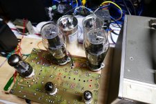
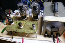
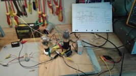
I have been working on the next generation of my TSE amp designs, and there is one connected up and running on my bench performing such an experiment shouldn't be too difficult, I could just remove the load from the OPT, but leave it in place to act as the plate choke. I would then wire up a large cap from the plate of the output tube to a load resistor, then return the load resistor to ground.
This amp is NOT and all DHT design, but the output stage is similar to that discussed here. One side of the filament is directly tied to ground. The grid is driven by a direct coupled mosfet follower which allows for A2 operation and eliminates blocking distortion. The plate goes to the OPT, which is fed directly from a CLC filtered 5AR4. B+ is about 340 volts with 45's. The driver tube is a 5842 high Gm triode, which is CCS loaded for very low distortion (around 0.2% at full output).
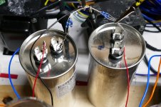
On paper a 10 uF cap is too small, so I grabbed a pair of 100uF motor run caps since I have plenty and they are quite good for audio. I didn't have any 32 ohm load resistors, but we are not talking big power here, so I wired 3 X 100 ohm 1% resistors in parallel.
I have no 6A4 tubes, and they won't fit my amp. The amp currently had 45's in it so I simply turned the idle current DOWN to 20 ma. I connected my cheap Philips DJ quality headphones up first. They are 32 ohms and capable of eating "2200 mW" so they have to be inefficient.....but efficiency is not specified. I have used these same headphones wired directly across the OPT output to check for low level hum, so I know how they sound on the same amp. Surprisingly they were quite LOUD, but not nearly as loud as directly from the 8 ohm OPT tap. The sound was good at lowish volume, but the bass got quite loose and boomy as I cranked it. It sounded worse than a SE pentode amp with no feedback connected to modern speakers. The mids and highs were clear and detailed, as good as through the OPT, possibly better on some music. Overall I preferred the OPT sound.
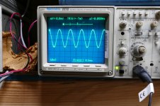
I connected up the scope, audio analyzer and oscillator. The oscillator I use is an old HP 204D that goes from 5 Hz to 1.2 MHz and makes about 0.1% THD through most of the audio range. 0.07% at 1KHz as measured on the HP8903A audio analyzer.
The measurements on the 45 based version were rather disappointing except for the frequency response. Cranking the drive up to force 20 mW of power brought flat topping and a THD in the 15% range. I had to reduce power to less than 5 mW to get under 5% THD. I tried another 45 tube, and the results were similar, but a little better. Cranking up the current improved things, but I didn't want to go much beyond 35 mA since my B+ is well over 300 volts. A quick twist of the frequency knob revealed rather flat frequency response to below my measurement limits.
In a quest to find out if this concept was valid at all (remember the OTL for guitar thread that blew up) I stuffed some 2A3's in the amp and tried again. Again, better but the amp was obviously starved for current, so what to do but turn it up! After all, the OTL guys use AMPS not milliamps. I cranked the 2A3's up to 70 mA. Now the results were better, and the amp SOUNDED much better. The bass was tighter and less boomy, and it would get loud enough to hear it across the room from the headphones.
Where I could barely squeeze 20 mW at 15% THD with 45's at 20 mA, now I'm getting 100 mW at 13%, 50 mW at 7.6%, 20 mW at 4.1%, 10 mW at 3.34%, 5 mW at 2.1%, 1 mW at 0.97% and 1/2 mW at 0.5%. The lower limit on THD in this setup is around 0.5% due to the loose wiring, and the main THD component is 60 Hz (not 120 Hz).
I set the analyzer up to measure frequency response, and was surprised. I set the 0dB point at 5 mW to avoid THD corrupting the readings. The lower 1dB point was below the 5 Hz limit of the oscillator, but the analyzer's level readings are not specified below 20 Hz. The level at 20 Hz was 0.02 dB below 1KHz. I'm using a 100 uF cap, so his 10uF might just be OK at 100 Hz.....
The level at 20 KHz was exactly 0dB. The upper 1 dB point comes at 52.2 KHz and the 3 db point comes at 72.3 KHz.
So far I still prefer that sound of the cheap Philips headphones through the OPT. I have not, and probably will not hook my Sennheiser's up to this thing......I will however stick some BIGGER tubes in it some time in the future.
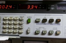
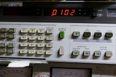
The scope and analyzer pictures were taken with 2A3's at 70 mA and 10 mW output. Picture 507 shows "watts into X ohms" where I input 33 for X (3 X 100 ohms in parallel). Picture 507 shows the THD as 3.34%.
Where is the difference in bondini's numbers coming from......maybe the idle current is not really 20 mA?
However the 32 ohm resistor across said inductor damps it's inductive properties quite seriously. What's possible in a real SE amp? There is only one way to find out. Try it.
I have been working on the next generation of my TSE amp designs, and there is one connected up and running on my bench performing such an experiment shouldn't be too difficult, I could just remove the load from the OPT, but leave it in place to act as the plate choke. I would then wire up a large cap from the plate of the output tube to a load resistor, then return the load resistor to ground.
This amp is NOT and all DHT design, but the output stage is similar to that discussed here. One side of the filament is directly tied to ground. The grid is driven by a direct coupled mosfet follower which allows for A2 operation and eliminates blocking distortion. The plate goes to the OPT, which is fed directly from a CLC filtered 5AR4. B+ is about 340 volts with 45's. The driver tube is a 5842 high Gm triode, which is CCS loaded for very low distortion (around 0.2% at full output).
On paper a 10 uF cap is too small, so I grabbed a pair of 100uF motor run caps since I have plenty and they are quite good for audio. I didn't have any 32 ohm load resistors, but we are not talking big power here, so I wired 3 X 100 ohm 1% resistors in parallel.
I have no 6A4 tubes, and they won't fit my amp. The amp currently had 45's in it so I simply turned the idle current DOWN to 20 ma. I connected my cheap Philips DJ quality headphones up first. They are 32 ohms and capable of eating "2200 mW" so they have to be inefficient.....but efficiency is not specified. I have used these same headphones wired directly across the OPT output to check for low level hum, so I know how they sound on the same amp. Surprisingly they were quite LOUD, but not nearly as loud as directly from the 8 ohm OPT tap. The sound was good at lowish volume, but the bass got quite loose and boomy as I cranked it. It sounded worse than a SE pentode amp with no feedback connected to modern speakers. The mids and highs were clear and detailed, as good as through the OPT, possibly better on some music. Overall I preferred the OPT sound.
I connected up the scope, audio analyzer and oscillator. The oscillator I use is an old HP 204D that goes from 5 Hz to 1.2 MHz and makes about 0.1% THD through most of the audio range. 0.07% at 1KHz as measured on the HP8903A audio analyzer.
The measurements on the 45 based version were rather disappointing except for the frequency response. Cranking the drive up to force 20 mW of power brought flat topping and a THD in the 15% range. I had to reduce power to less than 5 mW to get under 5% THD. I tried another 45 tube, and the results were similar, but a little better. Cranking up the current improved things, but I didn't want to go much beyond 35 mA since my B+ is well over 300 volts. A quick twist of the frequency knob revealed rather flat frequency response to below my measurement limits.
In a quest to find out if this concept was valid at all (remember the OTL for guitar thread that blew up) I stuffed some 2A3's in the amp and tried again. Again, better but the amp was obviously starved for current, so what to do but turn it up! After all, the OTL guys use AMPS not milliamps. I cranked the 2A3's up to 70 mA. Now the results were better, and the amp SOUNDED much better. The bass was tighter and less boomy, and it would get loud enough to hear it across the room from the headphones.
Where I could barely squeeze 20 mW at 15% THD with 45's at 20 mA, now I'm getting 100 mW at 13%, 50 mW at 7.6%, 20 mW at 4.1%, 10 mW at 3.34%, 5 mW at 2.1%, 1 mW at 0.97% and 1/2 mW at 0.5%. The lower limit on THD in this setup is around 0.5% due to the loose wiring, and the main THD component is 60 Hz (not 120 Hz).
I set the analyzer up to measure frequency response, and was surprised. I set the 0dB point at 5 mW to avoid THD corrupting the readings. The lower 1dB point was below the 5 Hz limit of the oscillator, but the analyzer's level readings are not specified below 20 Hz. The level at 20 Hz was 0.02 dB below 1KHz. I'm using a 100 uF cap, so his 10uF might just be OK at 100 Hz.....
The level at 20 KHz was exactly 0dB. The upper 1 dB point comes at 52.2 KHz and the 3 db point comes at 72.3 KHz.
So far I still prefer that sound of the cheap Philips headphones through the OPT. I have not, and probably will not hook my Sennheiser's up to this thing......I will however stick some BIGGER tubes in it some time in the future.
The scope and analyzer pictures were taken with 2A3's at 70 mA and 10 mW output. Picture 507 shows "watts into X ohms" where I input 33 for X (3 X 100 ohms in parallel). Picture 507 shows the THD as 3.34%.
Where is the difference in bondini's numbers coming from......maybe the idle current is not really 20 mA?
Attachments
Just another data point.
I know that an OPT that is too big for the application can be just as bad as oine that's too small....all that extra iron sucks up the details...
So I dug through my box of dead projects and rescued a pair of very old Edcor XSE15-8-5K OPT's. These might be just right.
I put back the 45's, set the bias to 25 mA and wired the headphone jack right across the OPT secondaries. No resistors....nothing. The amp is dead quiet with about 250 microvolts of noise across the headphones. As expected it's loud, but the bass is solid no matter how loud I crank it. This combination is the best sounding of anything I tried today.
I wired the 33 ohm loads across the secondaries and did some testing. At any sane power level, 1 mW to 100 mW the THD is between 0.2% and 0.3%. The lower 3 db point is 17 Hz and the upper is 54.3 KHz. The THD at 10 mW is below 0.4% down to 80 Hz where it rises to 1.9% at 20 Hz.
Maximum power output was also a surprise. The THD at 1 watt was 1.2% and clipping measured at about 3 watts. I didn't believe the numbers until I touched the load resistors and burned my finger.
Forget 19 mW at 0.04% or 30 mW at 0.12%. They do not make any sense.

45, please use your skill and knowledge to build, measure and report your results. Please report what might be useful in the approach I have taken and correct the errors that I have made.
Bondini
The real circuit is different than the one that appears on the schematic, one battery for two valves.
Cathode circuit of V2 is short circuited to ground on the battery.
Clearly seen on your own pictures, can you explain that?
What is the real circuit that you have measured?
Attachments
The real circuit is different than the one that appears on the schematic, one battery for two valves.
Cathode circuit of V2 is short circuited to ground on the battery.
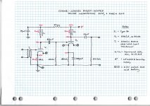
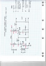
Thank you popilin - I can see two mistakes on my schematic and have attached a corrected version including pin numbers:
- There IS a connection from the anode of V1 to its choke.
- The is NO direct connection from signal ground at the base of the 68 Ohm cathode resistor of V1 to the lower leg of V2's 47 kOhm grid resistor
Yes, the signal ground for V1 AND the negative cathode pin No.5 of V2 are connected to the same negative terminal of the lead acid cell that heats their cathodes.
Attachments
Just another data point. I dug through my box of dead projects and rescued a pair of very old Edcor XSE15-8-5K OPT's. I put back the 45's, set the bias to 25 mA and wired the headphone jack right across the OPT secondaries.
Hi Tubelab,
Thanks for taking a constructive 🙂 approach and for putting in so much effort. I appreciate the time you have taken to explore the idea and report measurements.
When I first built the 6A4 circuit, I had no suitable SE output transformers and so resorted to the chokes I had at hand. I have ordered and am waiting for a pair of OPTs to try with the 6A4s (here:https://docs-apac.rs-online.com/webdocs/1528/0900766b81528917.pdf. These little OPTs are specified for use with EL84s. I will hook them up and will report results - however, I will not get back to the bench for a week or so.
Bondini
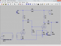
From your picture it seems that the real circuit is more or less similar to the attached one.
Attachments
Last edited:
Hi Popilin,
We agree - I have attempted to describe what you have drawn. Your schematic is clearer - thank you.
Bondini
We agree - I have attempted to describe what you have drawn. Your schematic is clearer - thank you.
Bondini
Dropping that OPT into your circuit should make a big difference. I think you will find enough power to blow the headphones off of your head. The OPT's that I have are of similar specs 5K to 8 ohms, but they are a little bigger (726 grams) and don't have the 16 ohm tap.
Popillin,
The only thing missing from the diagram is a source for the 60mA of heater current that runs through through R1, in addition to the 3mA anode current.
Bondini
The only thing missing from the diagram is a source for the 60mA of heater current that runs through through R1, in addition to the 3mA anode current.
Bondini
Also missing the battery, I have no DHT symbol, sorry, but now the circuit is more close to reality, especially the ground.
Sadly it was very difficult to decipher the circuit, your task, not mine...
Fortunately you are a great photographer! 😛😀
Sadly it was very difficult to decipher the circuit, your task, not mine...
Fortunately you are a great photographer! 😛😀
Last edited:
We are getting close! Please pardon my schematic illiteracy - I didn't draw a battery but indicated a single battery with two leads coming from the positive terminal and two from the negative terminal.
For the type 30, the positive terminal of the battery connects to pin 1, the negative to the base of the 68 Ohm cathode resistor.
For the 6A4/LA, the positive battery terminal is attached to pin 1 and the negative to pin 5.
Put another way, Pin 1 of V1 and Pin 1 of V2 are connected to the positive terminal of the 6.3V sealed lead acid battery; and the base of V1's 68 Ohm cathode resistor and pin 5 of V2 are connected to the battery's negative terminal.
Why? I had one 6.3V battery.
Hi Merlin,
I repeated the experiment with much better layout and found the output impedance at 1kHz was approximately 3400 Ohms. Positive numbers this time!
Bondini
Your schematic shows 10V at pin 5 of V2. Please remeasure, it is likely 0V. Also remeasure anode voltage of V2 to find current.... Yes, the signal ground for V1 AND the negative cathode pin No.5 of V2 are connected to the same negative terminal of the lead acid cell that heats their cathodes.
You have a wire connecting signal ground of V1, negative terminal of lead acid battery connected by another wire to pin 5 of V2 at 10V? If your measurement is correct then there is a wire with 10V potential difference from end to end.
Last edited:
Hi Indra,
I see your point - I have not correctly referenced the voltage measurements for V1. My schematic evolved along with a rats nest prototype - Popillin has posted a tidier version that accurately reflects V1 voltages elevated by 10V relative to a signal reference at the base of V2's cathode resistor.
The extra 10V can be "lost" across the 27 kOhm dropping resistor from the B+ supply.
The currents are accurate.
Bondini
And, what is the actual RDC of the 158L (datasheet says max 411 ohms, but actual would be better in troubleshooting)? And what voltage over it?
It isn't because here we are rating continuous power and even using the 100 years old 5% THD limit it is linearity that sets this limit. Extra power due energy storage can only be used in musical regime, for short transients, because distortion is high.Under ideal conditions it is possible for the peak current in a class A SE amp to approach twice the idle current due to energy storage in the output inductor. This is the same principle that allows the peak voltage to approach twice the B+ supply voltage.....
Your measurement proves my point. The 45 is representative for the 6A4 more than the 2A3. The 45 at 150V/20 mA has a plate resistance of 2K so it is already an optimistic limit for the 6A4 that has got about 3K in the same conditions. If 15% is the distortion of the 45 at 20 mA then it will not be better for the 6A4. Likely 20%. This cannot be rated as continous power by any standard.In a quest to find out if this concept was valid at all (remember the OTL for guitar thread that blew up) I stuffed some 2A3's in the amp and tried again. Again, better but the amp was obviously starved for current, so what to do but turn it up! After all, the OTL guys use AMPS not milliamps. I cranked the 2A3's up to 70 mA. Now the results were better, and the amp SOUNDED much better. The bass was tighter and less boomy, and it would get loud enough to hear it across the room from the headphones.
Where I could barely squeeze 20 mW at 15% THD with 45's at 20 mA,
This what I suspected in the beginning. Or his THD instrument is not really calibrated....Where is the difference in bondini's numbers coming from......maybe the idle current is not really 20 mA?
- Home
- Amplifiers
- Tubes / Valves
- The all DHT SET Headphone Amp