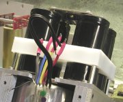
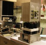
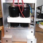
Peter Daniel said:Before I start sending the boards out, I have to test them, so today I was working on a power supply. Here what it looks like: 500VA Plitron is on the bottom, in its own enclosure. The Sikorel caps above (22,000/50) have ground terminals connected by 1/8" copper plate. This PS is for two channels, each channel having a pair of caps connected directly to a bridge.
You can see heatsinks in a back.
Looks really nice. I look forward to seeing how the final amp will work out.
What voltages is your transformer putting out?
--
Brian
The finishing touch will be to have gentle wisps of smoke (not magic smoke) puff from the top. It will look like a nuclear reactor letting off steam. 😉
There will be enough boards for everybody. I'm ordering more, but have to test the circuit first; hopefully tomorrow.
Drop me an e-mail for payment info.
Drop me an e-mail for payment info.
An Aleph in 2 days
So the amp is finished, and luckily it works fine. I have to admit that I was a bit uncertain about the outcome, as after all this is not a GC, but a manly amp 😉 This is also my first Aleph that does not hum.
The voltage I'm getting on rails is exactly 27.6V DC with a mains at 123V AC. The transformer is one per two channels, Plitron rated 2 x 20V , 500VA. With 115v rails you should be getting close to 25V though. The circuit is exactly from Aleph30 schematic.
Attachments

The fan supply is run from a separate windings, and by using an dajustable regulator (on the right, beside big caps) one can adjust the speed. It is pretty efficient setup, does not produce noise, and lowers temp. substantially.
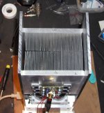
The plate that bridge is mounted on, runs cool enough, but differencial pair and const current source mosfet, are quite hot (more than 50 deg) so I will be probably using a strip of copper to lower temp (there is enough space for that).
The plate that bridge is mounted on, runs cool enough, but differencial pair and const current source mosfet, are quite hot (more than 50 deg) so I will be probably using a strip of copper to lower temp (there is enough space for that).
Attachments
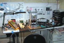
You can see that the chassis is slightly less ordinary. I'm always looking for different ways to implement circuits. Although I'm not much into circuit designing aspect, I take great pleasure in mechanical design.
You might find some influences from recent ML amps, although more could be sourced to Niro Nakamichi and his Mechanical Research Corporation projects.
I find it quite appropriate to use transformer at the very bottom, with all subsequent PS components stacked higher up, creating sort of a tower, separating transformer from the active circuitry, using very small footprint with the heatsinks at the very top, creating easy way for air flow and heat dissipation.
I'm quite satisfied.🙂
This board seems like a good starting point to move into Aleph X design, where two boards are used only for output stages only and ona additional board (in between) used for input circuitry. This creates well balanced halves and possibility to upgrade. I will be coming with one soon 😉
I will also try to sent out all the boards before Friday. Unfortunately, there is not enough for everybody ( I only ordered 50, in case the cercuit would have unpredicted error), but since it's working fine, I'm ordering more this week and should have them ready before next Friday.
Attachments


I need more time for any serious evaluation. The amp is not broken in yet. 😉
The fan is moving air up.
The fan is moving air up.
Member
Joined 2002
Without a fan, yes. Could be probably managable ( maybe 65 deg or so) but I didn't want to push it. With a fan it's about right temp (around 45 deg I suspect)
Great!
Peter,
Can you please post the approximate dimensions of the chassis and relevant bits.
I looks great!
Cheers.
Ryan
Peter,
Can you please post the approximate dimensions of the chassis and relevant bits.
I looks great!
Cheers.
Ryan
The chassis is 6" wide, 6.5" deep. The panels are 1/4 thick. The top of the heatsink is 16" from the bottom, with heatsink size 7.5 x 6 x 2.25
nbaula said:Hi! Peter do have any extra board I can buy ?
My 3rd e-mail to you have bounced, can you provide an alternative contact info?
Member
Joined 2002
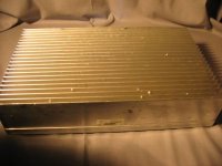
These heat sinks might be good for your a 30's.
Steve @ APEX JR has six heat sinks in stock they measure 14" X 8 1/4" X 3" tall. They have 22 fins, there is a half inch of solid aluminum before the fins start. They weigh 25 pounds each. They are USED
Flat bottom.
Priced at $ 62.50 each
Steve @ APEX JR has six heat sinks in stock they measure 14" X 8 1/4" X 3" tall. They have 22 fins, there is a half inch of solid aluminum before the fins start. They weigh 25 pounds each. They are USED
Flat bottom.
Priced at $ 62.50 each
Attachments
- Status
- Not open for further replies.
- Home
- Amplifiers
- Pass Labs
- The Aleph30 PCB layout