
Peter Daniel said:
I noticed that p2p slows me down.
I noticed that PCBs slow me down. Point-2-point construction allows me to sit down and stop fretting about the layout. I shuffle the parts around until it looks reasonable, then I solder them together. Last night I built the front end of my second Aleph-X, using p2p, in a 2"x1" board, and only taking about 30 minutes.
I love that old-timey 3-D construction.
That is true, but the thing that slows me down is the time I need to finally decide to sit down and do the circuit😉. Also first circuit, if needed to be done nicely, takes almost the same time as designing a PCB, subsequent assemblies are much faster and probably only twice the time required to put together a similar PCB. I love it too.
the herding instinct.......
I'm a loner in life and this is the only time I bother to join the herd.
The pcb process is hard to get rolling, but it's a great feeling to belong to a group of people such as this. The pcb helps to ensure that almost anyone can join in and savor the experience.
By the way, does anyone have a bunch of IRFP9240s they want to sell or trade for IRF240s?
John
John, are you one of those real northwesterner bushmen  that go to town once a month for supplies?
Just kidding,.
anyways I could use say 8 matched 240, I plan to experiment with both 044 and 240 too see what's up with that.
Let me know what you need, I am always about to make and order somewhere. email me.
that go to town once a month for supplies?Just kidding,.
anyways I could use say 8 matched 240, I plan to experiment with both 044 and 240 too see what's up with that.
Let me know what you need, I am always about to make and order somewhere. email me.
Why are we using great giant heat sinks on the input differential pair. Unless I am reading the schematic incorrectly, each FET in the pair is passing about 25mA and dissipating very modest power. In my prototype I've put the two fets back-to-back with a sil-pad and the heat is barely noticeable.
To mask or not to mask?
Brian,
Looks good.
I have one question about boards with solder masks. How does it affect the sound? I have found that they can affect the sound and several manufacturers refuse to use solder masks even if it helps in manufacturing boards.
Maybe some members could shed some light on their experiences.
Jam
Re: To mask or not to mask?
I am thinking of getting boards made by a manufacturer, and you can save a bit of cash on the boards if you skip the solder mask. I am considering keeping the soldermask, but skipping the silkscreen. The boards still will cost a bit, since they are 6" x 6".
I don't like boards without a soldermask, as it causes too many soldering problems. Also, without a soldermask, components aren't as insulated from the traces, which I would see more problems caused by this. If I am not careful on my leach amp board that I had made without a soldermask, then I can have the heatsink short my signal and ground trace.
I like the way that Joze's boards came out, and look much better then my boards (seen a few posts above). My boards are just a doubled sided milled copper pcb board dipped in tinning solution. I had a board etched without the tinning solution, but I like the ones with the tinning solution better, as long as it is fresh and it doesn't sit too long. I had to scrub the pads, then apply flux paste before soldering to the bare copper board.
--
Brian
jam said:Brian,
Looks good.
I have one question about boards with solder masks. How does it affect the sound? I have found that they can affect the sound and several manufacturers refuse to use solder masks even if it helps in manufacturing boards.
Maybe some members could shed some light on their experiences.
Jam
I am thinking of getting boards made by a manufacturer, and you can save a bit of cash on the boards if you skip the solder mask. I am considering keeping the soldermask, but skipping the silkscreen. The boards still will cost a bit, since they are 6" x 6".
I don't like boards without a soldermask, as it causes too many soldering problems. Also, without a soldermask, components aren't as insulated from the traces, which I would see more problems caused by this. If I am not careful on my leach amp board that I had made without a soldermask, then I can have the heatsink short my signal and ground trace.
I like the way that Joze's boards came out, and look much better then my boards (seen a few posts above). My boards are just a doubled sided milled copper pcb board dipped in tinning solution. I had a board etched without the tinning solution, but I like the ones with the tinning solution better, as long as it is fresh and it doesn't sit too long. I had to scrub the pads, then apply flux paste before soldering to the bare copper board.
--
Brian
jwb said:Why are we using great giant heat sinks on the input differential pair. Unless I am reading the schematic incorrectly, each FET in the pair is passing about 25mA and dissipating very modest power. In my prototype I've put the two fets back-to-back with a sil-pad and the heat is barely noticeable.
I just saw the big heatsink used on the pass labs XA, and I figured that I would use the same heatsink for my diff pair. That is the only reason.
--
Brian
Attachments

Nelson Pass said:That's a good reason!
😉
why not 🙂
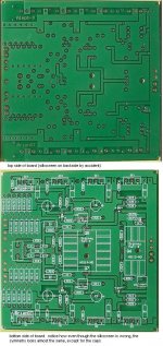
here is another picture that he sent me of the board. Notice how some of the pads were covered in silkscreen, since he got it on the wrong side of the board.. but it is interesting to see how the symmetry is pretty close, so you hardly notice that it is inverted...
--
Brian
Attachments
Brian,
Good looking board, who made it and how much did they charge? Did your friend only get one set made?
Thanks, Adrian
Good looking board, who made it and how much did they charge? Did your friend only get one set made?
Thanks, Adrian
kiwi_abroad said:Brian,
Good looking board, who made it and how much did they charge? Did your friend only get one set made?
Thanks, Adrian
I don't know the details. I mailed him the files about a week ago and he mailed me pictures of his boards today. He is located in Slovenia. I think that he just got one pair made, and wanted to try out all of the Aleph-X designs posted on the forum.
I had my boards made by the school. There are two bulk pcb orders going on now on the forum for Aleph-X pcbs, so I won't organize one myself also. I also want to do another revision of my board, once I make sure that this version works good. My parts are here tommorrow from digikey, so I can start populating the board.
--
Brian
Slovenia? It is quite close to me... (Italy).
Who is the member you were talking about?
I'd like to contact him and see if is possible to get a couple of boards.. maybe...
Andypairo
Who is the member you were talking about?
I'd like to contact him and see if is possible to get a couple of boards.. maybe...
Andypairo
Brian,
Whatever be the type of PCBs, with tinning, solder-masking, silk-screen etc., it would be cheapest probably in India.
I could help make boards from either Glass Epoxy(Green or White tint) or Composite material with Copper thicknesses of either 35, or 70 or 100 microns - your choice - and still keep the costs really down.
Please let me know if any help is needed in this regard.
Aleph X modifications
I've looked at the Aleph X lay-out and feel that the LM329(D1b) used to replace 1N5239B(9.1V zener) and also using the constant current diode J505(Q12a) linked to the negative rail would give a significant improvement in sound quality over the other Alephs.
Can I install similar modifications into the aleph 2?
ckt
hello BrianGT
hello, BrianGT
what software did you use to draw the pcb of Aleph-X.
your pcb drawing is very good. i think i can not draw this like you.
so can you give me the pcb file ? i want to modify your pcb file for my aleph-x.
if you use protel or tango software, it is better to me.
on this forum thread ,you only post the gif file (picture). i dont know how to modify the gif file to suit my aleph-x .
thank you for help .
Andypairo said:Slovenia? It is quite close to me... (Italy).
Who is the member you were talking about?
I'd like to contact him and see if is possible to get a couple of boards.. maybe...
Andypairo
He goes by jazzy on the forum:
http://www.diyvideo.com/forums/member.php?s=&action=getinfo&userid=3337
--
Brian
- Home
- Amplifiers
- Pass Labs
- The Aleph-X