Just like Nelson...
I just thought since early posts discussed 30 Ohms and that was suggested by Nelson it might be worth a test. I seem to recall something about 1K helping but reducing would be better and as 30 was suggested...
Just a suggestion though...
/UrSv
I just thought since early posts discussed 30 Ohms and that was suggested by Nelson it might be worth a test. I seem to recall something about 1K helping but reducing would be better and as 30 was suggested...
Just a suggestion though...
/UrSv
I am afraid to say this. If all are matched and done according to the drawing,
I might include possibility of oscillation problem in the check list.
JH
I might include possibility of oscillation problem in the check list.
JH
I was thinking that too since I suspect no compensation caps are used, most likely...
I was however afraid that there would be somebody else than me that wanted to say that...
/UrSv
I was however afraid that there would be somebody else than me that wanted to say that...
/UrSv
Let me give you an example:
The first channel readings at start up was 1.8V absolute offset with 4mV difference on both sides. Half an hour later it was 0.6V with 6mV difference between sides. After 2 hours it was -0.6V on both sides with difference of 8mV. When I was observing that I thought I was dreaming.😉
Now the second channel, on one side the absolute DC offset is about 0.1V at start up and it wonders up maybe to 0.2V after warm up. The other side though is more like 5V in the beginning and then goes down to 1V, it can be adjusted to lower value, but then drifts away again. So the difference is usually around 0.5V eventualy.
I have to find what is causing that kind of behaviour. I don't think it has to do anything with resistors or capacitors, but rather with semis and I have to figure out which ones.
Peter,
I have had the same problem before and it turned out to be a noisy mosfet which checked good on a semicoductor analyser.
Probably the best way to trouble-shoot is to start swapping parts between the good and bad channels till the problem moves to the other channel and you would have found your defective part, assuming it is not a wiring error.
Jam
Would there by chance be any reason to believe that swapping parts one by one is harder when you have built P2P?
/UrSv
/UrSv
Teething Troubles....
Peter, a hair dryer and can of freeze spray (you don't need much) are good for tracking down noisey semiconductors.
The noisey behaviour you describe sounds like an early failure, and is to be expected perhaps.
The other way to track it down is to do a channel-channel swap of suspected transistors.
Hope this helps.
Eric.
UrSv said:Would there by chance be any reason to believe that swapping parts one by one is harder when you have built P2P?
/UrSv
You bet it is😉
Sorry Peter, couldn't resist. Hopefully you find the problem quickly and without to much ripping apart.
Good Luck
UrSv
Good Luck
UrSv
What would be a recommended set of tests I should perform using scope and generator on the amp? Usually I run a sinewave through the frequency spectrum, but since it's an experimental design I might go few steps further.😎
Try driving a square wave sweep as well. Try both sine and square into an inductor, resistor, capacitor, and a dead short.
Good luck getting that fixed. I would also run square waves through it.
I got my boards yesterday, and will start populating them next week when I get my digikey order of parts. The guy made a small mistake milling them, but it can easily be fixed with a exacto knife.
(boards are 6"x6" square. the fisheye effect is from the close positioning of my camera)
--
Brian
I got my boards yesterday, and will start populating them next week when I get my digikey order of parts. The guy made a small mistake milling them, but it can easily be fixed with a exacto knife.
(boards are 6"x6" square. the fisheye effect is from the close positioning of my camera)
--
Brian
Attachments

Doing It The Hard Way....
The transistor by transistor channel swap is the only real way to track the problem down, elsewise replace with new semis stage by stage and see what you get. 😉 (I've had to do this swapping plenty of times in servicing - PITA but it can be quicker and easier).
The hair dryer and freeze spray can make the process faster too.
Hurry up and fix it so you can tell us the sound of your new love child. 🙂
Regards, Eric.
Some Advice From An Old Hand....
"I got my boards yesterday, and will start populating them next week"
Brian, your boards look good, but your gunna need a big soldering iron to solder some of those pads properly.
In my experience of long term reliability, do not be fooled by solder taking instantly to the pre-tinned surface - it takes an appreciable time for the solder to alloy into the surface of the copper tracks properly, and soldering and then desoldering and then resoldering helps to ensure a long term reliable and sonically good joint, and preheating (cooking) with a hair dryer helps a lot, especially for heat sucking fibreglass boards.
Also vias are not to be trusted long term on hot running pcb's - good to fill them with solder or a short wire stub in my experience (unreliable hot running high power pro-amps with double sided boards).
Solder masking would be a great asset on your boards, as it limits the the area of each solder joint, and this greatly assists solderabilty and helps greatly to eliminate solder bridges.
Good luck with your new baby,
Eric.
(I'm In for a low power, lower cost version using a PC SMPS.)
Hint - if you ask your pcb maker he might give you some solder resist laquer that you can apply around pads with a small art brush and then bake the board in a bench top toaster-oven.
Re: Some Advice From An Old Hand....
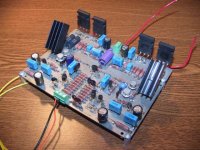
Thanks, my last boards that I got made didn't seem to have any problems soldering (picture attached).
I am using a weller wpcpt soldering station, that seems to keep the tip at a constant 700 degrees (i have an 800 degree tip also). It should work alright, but if I have problems, I have a friend with one of those high voltage solder gun looking things that I can borrow.
As for the board treatment, he had no suggestions. He just changed the tinning solution, so it should solder well. I will keep extra flux on hand for this also.
As for the boards, I might get a couple of pairs made. I think that I can get a pair made for $50 if I get a few friends in on it (heavty copper, soldermask, silkscreen). I am going to finish these prototype boards first and see what kind of revisions that I want to make. I think that Peter was right about the orientation of the output devices, while near perfect symmetry is good, mounting won't be as easy as hoped.
--
Brian
mrfeedback said:
Brian, your boards look good, but your gunna need a big soldering iron to solder some of those pads properly.
In my experience of long term reliability, do not be fooled by solder taking instantly to the pre-tinned surface - it takes an appreciable time for the solder to alloy into the surface of the copper tracks properly, and soldering and then desoldering and then resoldering helps to ensure a long term reliable and sonically good joint, and preheating (cooking) with a hair dryer helps a lot, especially for heat sucking fibreglass boards.
Also vias are not to be trusted long term on hot running pcb's - good to fill them with solder or a short wire stub in my experience (unreliable hot running high power pro-amps with double sided boards).
Solder masking would be a great asset on your boards, as it limits the the area of each solder joint, and this greatly assists solderabilty and helps greatly to eliminate solder bridges.
Thanks, my last boards that I got made didn't seem to have any problems soldering (picture attached).
I am using a weller wpcpt soldering station, that seems to keep the tip at a constant 700 degrees (i have an 800 degree tip also). It should work alright, but if I have problems, I have a friend with one of those high voltage solder gun looking things that I can borrow.
As for the board treatment, he had no suggestions. He just changed the tinning solution, so it should solder well. I will keep extra flux on hand for this also.
As for the boards, I might get a couple of pairs made. I think that I can get a pair made for $50 if I get a few friends in on it (heavty copper, soldermask, silkscreen). I am going to finish these prototype boards first and see what kind of revisions that I want to make. I think that Peter was right about the orientation of the output devices, while near perfect symmetry is good, mounting won't be as easy as hoped.
--
Brian
Attachments
Doing It Right.....
Use of plenty of good solder and a varitemp iron are mandatory IME.
Also clean (polish) the solder wire, component leads and the pcb to remove oxides with tissue and solvent (isopropyl) before you start.
Do this properly and it will never let you down.
Eric.
Peter Daniel said:From my experience high power soldering iron (50W or so) is very helpful.
Use of plenty of good solder and a varitemp iron are mandatory IME.
Also clean (polish) the solder wire, component leads and the pcb to remove oxides with tissue and solvent (isopropyl) before you start.
Do this properly and it will never let you down.
Eric.
- Home
- Amplifiers
- Pass Labs
- The Aleph-X