Re: I'm on a Macintosh........
Have you seen this article?
http://sound.westhost.com/power-supplies.htm
22 VAC with a full-wave bridge, lightly loaded, will give about 22*1.4 = 30.8 VDC. Accounting for the load you should still get (maybe) 26VDC; with the LC and 4 volts for the FET you'd still be up around 20VDC. You can regulate it down to 15V but you're just throwing away power; better to start with a lower voltage transformer.carpenter said:Working with one side of a dual in/out transformer, I took 22 volts x 0.9 (LC power drop) = 19.8 volts - 4 volts (FET drop) = 15.8. I missed the first calc by 0.2 (called the final voltage 15.6), my mistake was caused by quoting the figure from memory.
John
Have you seen this article?
http://sound.westhost.com/power-supplies.htm
Re: Re: I'm on a Macintosh........
Carpenter has it correct. Because the inductor is the 1st element after the bridge, the resultant multiplier is 0.9 not 1.4 assuming that the inductance is equal to or greater than the critical inductance for the given circuit.
paulb said:
22 VAC with a full-wave bridge, lightly loaded, will give about 22*1.4 = 30.8 VDC. Accounting for the load you should still get (maybe) 26VDC; with the LC and 4 volts for the FET you'd still be up around 20VDC. You can regulate it down to 15V but you're just throwing away power; better to start with a lower voltage transformer.
Have you seen this article?
http://sound.westhost.com/power-supplies.htm
Carpenter has it correct. Because the inductor is the 1st element after the bridge, the resultant multiplier is 0.9 not 1.4 assuming that the inductance is equal to or greater than the critical inductance for the given circuit.
R1 question on Z4 p.s. (still trying for that 15 volts)
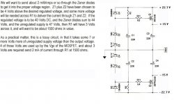
It seems to me (correct me if I'm wrong) that Nelson knows that there's a need for 3 additional volts to drive voltage through R1. Now, in my case, I have 22.7 volts after LC filtering. I adjust my zener layout to sum up to 19 volts (15 +4) and then subtract it from 22.7 to get 3.7 volts. This 3.7 volts is divided by 0.002 (as in milliamps) to arrive at 1850. Now, is this the size resistor that I'd use in R1?
John Inlow
That's right John, basically you want to give the zener slightly above it's voltage rating and let it do some work, the zener will sink some current to bring the voltage down to 19V. Too much over voltage will kill the zener because it won't be able to handle all the current in needs to shunt. If you go below 19V the zener becomes useless. How much current it can sink depends on the zener power rating.
Thanks for input, grataku
I'm delighted to have learned something new. It neat how Ohm's law works, the problem for me is how to lay out the problem.
John
I'm delighted to have learned something new. It neat how Ohm's law works, the problem for me is how to lay out the problem.
John
Oh right, the LC doesn't give you 1.4x. AudioFreak says 0.9x, okay (I would use the PS simulator to do this; I've never used an LC).
7 volts drop at 4.5A is over 30 watts. John, you might also consider a bipolar transistor-based capacitance multiplier. It has far less voltage drop (and therefore power wasted) than a FET regulator.
Check out
http://sound.westhost.com/project15.htm
and
http://www.gmweb.btinternet.co.uk/jlhcapmult.htm (I would use the Fig. 2 circuit).
The point is ripple reduction; I think actual regulation of voltage is only a secondary concern with a Class A amp.
After finally figuring that 3,000 ms means 3 sec and not 3.0 msec, I had quite a bit of fun with the power supply simulator. I think it's a essential too in understanding things like ripple current, where one's biggest cap should be for maximum noise reduction etc. In essence, I think I narrowed it down to 13-14Vac transformer, and a pi filter made up by 2 100mF and 0.3-0.5 ohms (thermistor or whatever). It will end up burining 10-25W channel to get a clean DC with 5-10mV ripple, there is nothing for nothing.
I think L is way too big and expensive for what you get in return.
I think CRC is better than RC or LC, the ripple current is a little bit better distributed.
Tomorrow I will call Victoria Magnetics and ask for prices. 800VA
4x13-14Vac 15-20A secondaries 2% regulation, and 2x115 primaries shields.
Has anyone else been contacting VM for about something similar?
Yessiree,
Both BrianGT and I have been in touch with John at VM about transformers for the Aleph-X. John has sent me a pair of trannies with a couple of different options to try (one with and one without the electrostatic screen). I'm eager to see what kind of results I can get with them. I think John may be willing to provide some sort of discount on his trannies for the Aleph-X, once some of the rough specs are worked out. The ones I asked for are a simple version with single 115V primary, 300VA, and dual 11V secondaries. Since I plan to use shottky rectifiers, and only one bridge per channel, I expect much less power loss in the rectification stage. With a CRC stage using about 0.25ohm resistance, I expect to get close to 11 or 12V rails out of it.
Anyway, I think jwb started a thread somewhere for Aleph-X trannies from VM... I still haven't read that thread yet, but I'm sure I'll be posting to it as I fiddle with the VM trannies and get some experience with them.
I don't know if you saw my another Aleph thread, but my transformer drops 4 V per rail under load. It is Plitron 750VA trafo with primaries in series to get lower voltage. No load voltage was 20V. When running it with 7A total draw, I'm getting 16V minus 1V drop on thermistors for final rail voltage of 15V. I'm using one per channel.
Peter Daniel said:I don't know if you saw my another Aleph thread, but my transformer drops 4 V per rail under load. It is Plitron 750VA trafo with primaries in series to get lower voltage. No load voltage was 20V. When running it with 7A total draw, I'm getting 16V minus 1V drop on thermistors for final rail voltage of 15V. I'm using one per channel.
hmm.. that sucks. I guess that your VA was cut in half by the series primaries. Are you going to get new transformers, or keep the lower power for now? Does the transformer get hot?
--
Brian
Transformers don't get that hot, mostly from the chassis probably. With that current draw, the limiting factor are heatsinks and I couldn't run the amp at higher voltage anyway. This amp is for mids/treble so it's enough power for now.
I have some problems with adjusting second channel. The absolut offset is different on both sides and it's drifting quite much (almost 1V). The other channel is right on point all the time with 6mv offset. 😕
I have some problems with adjusting second channel. The absolut offset is different on both sides and it's drifting quite much (almost 1V). The other channel is right on point all the time with 6mv offset. 😕
Sorry to hear...
How the other identical channel could meet the strange problem...?
No idea, but possible error during the assembly...?
I hope you will fix it soon.
JH
How the other identical channel could meet the strange problem...?
No idea, but possible error during the assembly...?
I hope you will fix it soon.
JH
Peter, I predict you'll find the problem sometimes today.
Will you be changing transformers in the end?
Will you be changing transformers in the end?
Peter,
Bad differential mosfet? Please tell us how it sounds as soon as you hook it up. A comparison between it and the Aleph would be nice.
Jam
Bad differential mosfet? Please tell us how it sounds as soon as you hook it up. A comparison between it and the Aleph would be nice.
Jam
Just one question concerning the Aleph-X amplifier, is it convert unbalanced to balanced itself?
SDF, yes.
Grataku,
I don't know if I'll will change transformers. Will see how the amp performs first. But with the existing heatsinks and curent I'm getting I can't use more voltage. Would be too hot.
Jam,
Differencial pair mosfets seem to be OK. I'm getting signal through and the voltage drop on 392ohm resistors is almost identical. I noticed that this was not an easy task to achieve. I had some pairs which measured the same, yet in circuit, the voltage drop on those resistors wa different.
I wonder if its the input pair or output stage or the active current circuit. It's just that one side is much more stable with DC offset and on the other side the DC offset slowly goes up (or down) much faster. So differencial offset is not stable.
OTOH, the first channel was perfect in this regard. Both sides DC component was changing exactly in the same way so I always got 0V at the output. Very interesting.
- Home
- Amplifiers
- Pass Labs
- The Aleph-X