Samuel Jayaraj said:Brian,
Whatever be the type of PCBs, with tinning, solder-masking, silk-screen etc., it would be cheapest probably in India.
I could help make boards from either Glass Epoxy(Green or White tint) or Composite material with Copper thicknesses of either 35, or 70 or 100 microns - your choice - and still keep the costs really down.
Please let me know if any help is needed in this regard.
A few of my co-workers are from Bangalore, and they always tell me how cheap it is to get boards made over there.
Wouldn't shipping and taxes be a hassle for this? What would customs charge?
--
Brian
Andypairo said:Slovenia? It is quite close to me... (Italy).
Who is the member you were talking about?
I'd like to contact him and see if is possible to get a couple of boards.. maybe...
Andypairo
Here is what he sent me:
Joze wrote:
>Hi Brian,
>
>Artwork on the wrong side - production mistake!!
>Producers price:
>up to 11pcs. = 16.5 US$ per board
>up to 51pcs. = 8 US$ per board
>up to 100pcs. = 7 US$ per board
>Price depend on currency excange rate (US$ - SIT)
>Production time 5 working days.
>Is there anythink to do for you??
>
>Best regards
>
>Joze
If you guys want to organize a bulk pcb order over there, go for it, and you are welcome to use my board files for this. My only concern is that although I think that my board layout is correct, I haven't tested it myself yet, so no guarantees. As long as no one is profiting from the Aleph-X design, I would see no problems with this.
He has my gerber files that he made the board with, so if he is willing, you guys can get a big batch of boards made.
--
Brian
Re: Aleph X modifications
This replacement was (originally, I think) suggested by Harry Haller (a.k.a. Fred Dieckmann) in this thread.
http://www.diyaudio.com/forums/showthread.php?s=&threadid=4295&highlight=noise+lm329
Then Peter implemented it into his AX project (look at some AlephX thread posts from around September of this year. You can also do a search on "noise" and "lm329".
I like the circuit myself and plan to use it in my Aleph 5. I've attached a zip file with a circuit drawing, and a word file with HH's (Fred's) explenation from one of his posts. Here's a link to National for the app notes.
http://www.national.com/ds/LM/LM129.pdf
Rodd Yamashita
diyman,diyman said:I've looked at the Aleph X lay-out and feel that the LM329(D1b) used to replace 1N5239B(9.1V zener) and also using the constant current diode J505(Q12a) linked to the negative rail would give a significant improvement in sound quality over the other Alephs.
Can I install similar modifications into the aleph 2? ckt
This replacement was (originally, I think) suggested by Harry Haller (a.k.a. Fred Dieckmann) in this thread.
http://www.diyaudio.com/forums/showthread.php?s=&threadid=4295&highlight=noise+lm329
Then Peter implemented it into his AX project (look at some AlephX thread posts from around September of this year. You can also do a search on "noise" and "lm329".
I like the circuit myself and plan to use it in my Aleph 5. I've attached a zip file with a circuit drawing, and a word file with HH's (Fred's) explenation from one of his posts. Here's a link to National for the app notes.
http://www.national.com/ds/LM/LM129.pdf
Rodd Yamashita
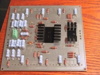
I got my parts today for my boards. I ordered the wrong caps... surface mount caps for the electrolytics... don't know how I managed that.
Here is a pic of the board. The components look pretty good on the board so far. I should finish it early next week after I get back from thanksgiving.
I have a real hard time getting good pictures of these boards, since they are so reflective. I can't use the flash, or put bright lights near it, so I have to hold the camera still for 1/4 of a second, which makes the pictures blurry... It does have image stabilization which helps a bit. (canon pro90is digital camera) Anyone have any tips for decent indoor pictures with a digital camera? I am used to outdoor photography.
Note on layout, I am currently using the 10pF caps from digikey that are used in the zen v4 article. I have more, and will series them to get 5pF later and try both on a scope once it is done. For the resistors, I meant to have 6 for each bank, but I ordered the wrong values (calculated the .22 ohm bank for 3 resistors, so I ordered .68 ohm resistors...).
As far as my next revision goes, I am going to make the device mount correctly on both sides (lose the symmetry, but not too bad), and make an allowance for Fred's CCS (allow both). I am still trying to decide if I want to make room on the boards for input caps. I will see about this later, once I find the caps that I want to use for sure. For now, I am going to use a pcb that mounts to the xlr jacks.
If you run this amplifier with a single rca connection, what do you do with the other unused input? ground it?
--
Brian
Attachments
Re: Long Exposure
What a great nickname... I hope that you stand up to the task for the ladies.
I will see if I can borrow a tripod for next time. The board looks soo much better in person.
The thick traces are soldering quite well also.
--
Brian
vinay said:Tripod.
Thats the term of endearment that the girls use for me!!!!
😀 😀 😀
Vinay
What a great nickname... I hope that you stand up to the task for the ladies.
An externally hosted image should be here but it was not working when we last tested it.
I will see if I can borrow a tripod for next time. The board looks soo much better in person.
The thick traces are soldering quite well also.
--
Brian
An externally hosted image should be here but it was not working when we last tested it.
sorry .BrianGT
sorry sir
because i am in china , i have any no visa ,no master card
, no paypal. i can not get any board pcb from outside china.
so i asked that shy question. i think i should do myself to clone your pcb. that is my only way to aleph-x.
sorry sir
because i am in china , i have any no visa ,no master card
, no paypal. i can not get any board pcb from outside china.
so i asked that shy question. i think i should do myself to clone your pcb. that is my only way to aleph-x.
Re: sorry .BrianGT
I can send you the gerber files. Would this work for you?
--
Brian
john-china said:sorry sir
because i am in china , i have any no visa ,no master card
, no paypal. i can not get any board pcb from outside china.
so i asked that shy question. i think i should do myself to clone your pcb. that is my only way to aleph-x.
I can send you the gerber files. Would this work for you?
--
Brian
BrianGT said:
If you run this amplifier with a single rca connection, what do you do with the other unused input? ground it?
--
I grounded it through the capacitor. In case of my high pass filter I used .12u caps on both inputs. The negative input (on the amp) connects to ground through the cap. Shield (from interconnecr) goes directly to the ground). Both caps have to have the same value, otherwise hum is observed. Also the grounding caps acts as a filter too, so the value has to be adjusted for that.
I also tried 100k resistor (input to ground) before the cap, and it influences the sonics: somehow cleans the sound, making everything more focused.
Input FETS for Aleph X
I just discovered that I have a bunch of 2SJ75 super matched dual audio FETs by Toshiba in a metal package leftover from an old project.
The main parameters are:-
V gds = 25V
Id = 10ma
Pd = 400mW/unit
gm 15-22 @ -10V vds
Ciss = 105pf
Crss = 32pf
Are the current and voltage ratings too low to be used to substitute the IRF9610s?
😕
Which preamp for Aleph X?..
which pre should one use for aleph x to get best results?
Pass line stage or aleph p 1.7? or ....?
or is it possible to connect the amp direct to the cd player for best results?
Ralf
which pre should one use for aleph x to get best results?
Pass line stage or aleph p 1.7? or ....?
or is it possible to connect the amp direct to the cd player for best results?
Ralf
I connected my amp directly to DAC's output. 24 position Elma switch is built into DAC.
I think it's up to you, your system and taste. It might be worthwile to compare if using additional preamp improves anything. I'm building P1.7 and XBSOZ, so I will check them out.
But somehow the idea of extra component in signal path doesn't appeal to me.🙄
I think it's up to you, your system and taste. It might be worthwile to compare if using additional preamp improves anything. I'm building P1.7 and XBSOZ, so I will check them out.
But somehow the idea of extra component in signal path doesn't appeal to me.🙄
Input FETs
Yes, its MilliSiemens. In fact, this audio FET together with 2SK146(N-channel) is regularly used as input devices by Erno Boberley in his amps. Its a metal clad dual package with a total Pw of 800mW. Matching and thermal coupling problems would be eliminated. My main concern would be the relatively low Vgs rating of 25V and Id of about 10ma as I intend to run the circuit at about +/- 22V. If it can be used, I believe there's a supplier here who still have a reasonable quantity at about USD3/- each and I may be able to get some for other forum members if they're interested. Would appreciate your advice.
😕
You can cascode it easily enough, arguably with better
performance. The transconductance is low compared
to the Mosfets, but it will still work. Figure on 5 ma of
current through each device of the diff pair and a 1 Kohm
Drain load.
If you need more poop on cascoding, see the cascoding
article at www.passlabs.com
🙂
performance. The transconductance is low compared
to the Mosfets, but it will still work. Figure on 5 ma of
current through each device of the diff pair and a 1 Kohm
Drain load.
If you need more poop on cascoding, see the cascoding
article at www.passlabs.com
🙂
BrianGT said:I got my parts today for my boards. I ordered the wrong caps... surface mount caps for the electrolytics... don't know how I managed that.
Here is a pic of the board. The components look pretty good on the board so far. I should finish it early next week after I get back from thanksgiving.
If you run this amplifier with a single rca connection, what do you do with the other unused input? ground it?
--
Brian
Some questions from a newbie to 2sided PCB's. I see you solder the components at the toplayer, are there also solderjoints at the bottomlayer?


finally finished reading 91 pages of Aleph-X thread

Peters thread about his p2p Aleph-X motivated me to read all of this.
Must say that as the pages past the information content slowly faded to zero with the occasional highlight here and there.
I´m still not shure if I´ll build one of these or my planned Aleph2´s .
A few of the descriptions of the sound, compared this to Alephs that were build on a different budget or with different bias etc. so no real comparison yet.
What are the theoretical advantages of an Aleph-X over an Aleph except for distortion? Is the output impedance lower (or twice as high)?
I found a few disadvantages too:
1. The efficiency is lower cause you need the 2 volts of distance to the rail twice. (an Aleph with 30V rail will have a higher power output than an X with 15V rails(28Vpeak to 26V peak))
2. The amount of caps in the power supply must be 4 times as high if you want the same same amount of energy stored.
So someone please convince me that I still have to build an X
😕
wuffwaff said:
The amount of caps in the power supply must be 4 times as high if you want the same same amount of energy stored.
But also they are of lower voltage, so probably cheaper and easier obtained.😉 My impression is that bass has more authority and highs are better defined, without being etched though.
The other problem you didn't mentioned is transformer, which for higher power version has to be custom made and more expensive.
I was also planning to built Aleph 2, but after seeing Nelson's pictures decided on an X.😉
My overall feeling is that this amp is more neutral than Aleph.
"2 volts of distance to the rail" is negligible IMO.
Peter Daniel said:
The other problem you didn't mentioned is transformer, which for higher power version has to be custom made and more expensive.
Why does it have to be custom? Would not any standard transformer work just fine?
/UrSv
From what I was looking at it's hard to find 500VA (or more) transformer with secondary windings of 12V. Usually they go up to 250VA only. I don't think you'll get double 15-17V secondaries, 1000VA, off the shelf.
- Home
- Amplifiers
- Pass Labs
- The Aleph-X