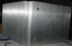
Your amp looks bold too. Nice work. For that caliber of a project maybe it would be worthwile to consider anodizing instead of painting? As to the screws you have on front panel now, I like to use them in all my projects. I mount them recessed, so they are flush with a surface. http://www.diyaudio.com/forums/showthread.php?s=&threadid=3981&perpage=15&pagenumber=5
it would be worthwile to consider anodizing instead of painting
Peter is correct, but more than that paint acts as an insulator and will cause the Aluminum to build up more heat because of a reduced thermal capacity.
Your Chassis looks excellent, carry that excellence through to the finished product.
Anthony
pcb cost
Hi guys,
A standard 6"x4" pcb with expected features cost as follows:
3 day prototype (no tooling fee):
10 pcbs at $38.70 each
7 day production (a one time $150.00 tooling fee to be split by the number of purchasers):
10 pcbs at $28.89 each
20 pcbs at $16.15 each
50 pcbs at $8.51 each
76 pcbs at $6.78 each
100 pcbs at $5.96 each
A four week lead time will reduce the pcbs to $4.26 each, but, who wants to wait that long?
If the pcbs are ordered in the "prototype" format, the tooling fee would be waived in future "production" orders.
I'll soon be posting artwork with drill size requirements. It seems wise to perform a double check with you guys prior to ordering.
How about some feed back?
John Inlow
huh?
I don't understand the question. If you're asking about the pcb artwork, I can't tell you exactly, because my audio pages may be setup for a different number of posts than yours. If you're asking about the drill size posting, it isn't up yet.
John Inlow
I don't understand the question. If you're asking about the pcb artwork, I can't tell you exactly, because my audio pages may be setup for a different number of posts than yours. If you're asking about the drill size posting, it isn't up yet.
John Inlow
I was asking about the artwork. What date is it posted then? You were asking for feedback, right?😉
Yeah, I want feedback......
It's going to take a few days to get the new artwork finished. I'm trying to work on my house, too (translation: wife wants dining room painted).
For the moment, feedback with regard to the pcb pricing would be nice.
John Inlow
It's going to take a few days to get the new artwork finished. I'm trying to work on my house, too (translation: wife wants dining room painted).
For the moment, feedback with regard to the pcb pricing would be nice.
John Inlow
feedback: this pricing looks much more friendly than that:
http://www.diyaudio.com/forums/showthread.php?s=&threadid=6935
http://www.diyaudio.com/forums/showthread.php?s=&threadid=6935
another price.....
I'm using pricing software on a pcb manufacturer's website. It suggests that if we wanted to avoid the $150.00 tooling fee we could purchase 40 pcbs (enough for 20 amplifiers) at the "prototype" rate of $11.18 each. This is excellent if only twenty of us want to give it a go.
John Inlow
I'm using pricing software on a pcb manufacturer's website. It suggests that if we wanted to avoid the $150.00 tooling fee we could purchase 40 pcbs (enough for 20 amplifiers) at the "prototype" rate of $11.18 each. This is excellent if only twenty of us want to give it a go.
John Inlow
I´m sure if you take your time to provide a really good PCB and wait until everyone made his descision (no problems with a few weeks - lower price) you should think about some more than 20 amps.
I could "contribute" to buy a set too if it would help to keep the price down to below or equal to $11.18 each even though I don't see myself building the amp any time soon.
more data......
Hi everyone,
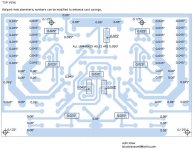
I've sent off my artwork and hope to hear from them next week. I haven't the ability to create gerber files, but they do. I've asked them to give me a price quote as well. I'll pass along any info as it arrives. Here's a pic of the drill sizing. All positive suggestions welcome. Any Trolls out there, please, go play with the fairies.
Hi everyone,
I've sent off my artwork and hope to hear from them next week. I haven't the ability to create gerber files, but they do. I've asked them to give me a price quote as well. I'll pass along any info as it arrives. Here's a pic of the drill sizing. All positive suggestions welcome. Any Trolls out there, please, go play with the fairies.
Attachments
thanks for the emails
Hi,
To everyone who emails me regarding the Aleph X pcbs: Thanks.
I'm placing your names in a special folder and will contact you when the red tape is done and the boards look like they're ready to be manufactured. At this point I'll want some working cash. If anyone else is interested in purchasing pcbs, please email me. It takes two pcbs per amplifier.
John Inlow
I would like a set for a pair of monoblocks
you have my commitment on a set for a pair of monoblocks
I also would like to comment that I think you have acted well and have handled this situation well.
😉
Ken L
you have my commitment on a set for a pair of monoblocks
I also would like to comment that I think you have acted well and have handled this situation well.
😉
Ken L
Looking at your artwork, Q5 and Q7 make differencial pair. They both should be thermally coupled. What kind of heatsink do you have in mind? Also, to make the traces simpler would it be better if Q11 gate connected with Q7 drain and Q2 gate with drain of Q5. You would have to run 2 traces under R22 but it's possible and the artwork would be less complicated. Just my first impression.

If it works, leave it alone
Hi Peter,
Wessol's board works. Therefore, I'm not planning to modify a pcb that's been fabricated and tested.
The differential pair has been layed out in such a fashion that the transistors can be coupled back to back. To fill the span between the two transistors, I plan on using a small piece of aluminum, or copper, with a heatsink mounted on top.
I can see where your idea for the redesign originates and it is clever, assuming the traces were renamed. I also can see where confusion would creep in with the hard wiring and someone gets Q2 and Q11 mixed up. We'd lose the X configuration.
- Home
- Amplifiers
- Pass Labs
- The Aleph-X