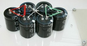
Glueing caps
I used Black RTV and drilled a few holes for the excess RTV to escape and aid the adhesion to the plexiglass. I would have mounted the caps inverted but I might add more caps and it would be a hassle to pull the board later for that. I also wanted easy access to the terminals to ease wiring and bypass changes I am trying real hard to make sure I can get at everything easily for later mods and parts changes. My stuff seems to evolve later and I hate taking everything apart to change two capacitors. The Passlabs Aleph 3 is great since you can pull a heatsink with three screws to get at the PCB. One of the easiest amps to mod Ihave ever owned... Thanks Nelson.
H.H.
the cutest amp I ever built
My wife said it looks like a toaster. WOMEN!!! I think it is way cool and kind of retro looking. I will deal with the wife later...
H.H.
My wife said it looks like a toaster. WOMEN!!! I think it is way cool and kind of retro looking. I will deal with the wife later...
H.H.
common mode feedback
Joe, thanks for your reply. I thought my idea was original but in retrospect it is not suprising that somebody else came up with it independently and well before me. Can't say I've heard of the Hadley - any chance of a schematic?
Encouraged or not, I wil plough on and try this out. Might be difficult to evaluate the sonic effects though, at least with any degree of objectivity.
Headphone X amp
Harry, I had the same idea regarding the simple diff pair, low gain, common mode servo. I'm not entirely sure whether the term servo is appropriate though as I wasn't intending to restrict its operation to very low frequencies. I'll post a schematic when I'm at home. I'd also be interested in yours.
Still not sure I understand the operation of the two resistors from outputs to ground although I can observe the effect easily enough.
originality
Ian, I don't think this schematic would survive further scanning; it's pretty rough. I'll see if I can find a better copy to post.
The basic idea of feeding a common mode signal to a constant current source for correction wasn't even new with Hadley. I've seen it in tube/valve circuits from the 1940's -- there may be a write-up in Valley & Wallman's Vacuum Tube Amplifiers, for example. A surprising number of "new" ideas are buried in those old tube texts . . .
Sorry if you found this deflating, but you can still take credit for coming up with the idea on your own. That alone proves your capacity for original thought. Better luck next time. 😉
Ian,
Bear with me while I bounce back and forth and see if I can respond to all your points in the time I've got...
--Sensitivity
The absolute DC offset is the same on both sides. As far as the driver is concerned, it doesn't exist, because there's no potential difference from one side to the other, hence no heating. Relative DC offset is a different matter entirely, but with matched components it's not that bad and can be adjusted with V1 and V3, anyway. The adjustment isn't as hairy as previous posts make it sound, at least not if you use a multi-turn pot. Or you could use the alternate values I posted for R24 and R26 to increase control. Or both. As a practical matter, the output pops up about 2 or 3 volts at turnon (don't panic, remember that it's not noticed by the driver--think SOZ output DC offset), then settles down towards 0V over the next few minutes. No, shorting the output to ground doesn't help; it's a thermal thing, and you just have to wait for the amp to heat up. Once the amp is warm, it's really pretty stable. Yes, it drifts some, but again, the speaker doesn't care.
--Output grounding resistors
Most output sections are connected to one side of the driver. The other side is connected to ground. When in operation, the output stage sees a fairly low Z (4 to 8 ohms) path to ground. The way this amp is designed, the output stage sees only the other output stage--not ground. The resistors serve to ground reference the output stages.
--A better solution?
Excellent! I'm all for it. I came up with this circuit idea over a year ago and mentioned it in Petter's X thread. (The concept wasn't well received at first...oh, well.) I spent until this past December getting to the general topology that you see now. Then Nelson warned me about DC offset, and just as I was getting ready to start experimenting (the Mini-A was just a stepping stone to get to this circuit), my computer was hit by a virus and I lost quite a bit of time. But...that doesn't mean I wasn't thinking about it. I do a lot of thinking about these things while I'm driving back and forth to work, and I wrote down pages of notes, trying to anticipate the various mechanisms involved and possible ways to solve them. Frankly, most of them didn't work, but then, I didn't expect that all of them would. In the end, it was a combination of two separate ideas that did the trick--adjusting the front end current source and grounding resistors. Neither one by itself will do it.
But is there a better way? Probably. I still have one or two ideas left in my notes, one of which is identical to what I think you're describing with resistors from the outputs to the front end Sources. I see two problems with this. One is the DC offset represented by the Vgs of Q5 & Q7. This will vary from device to device, and I could never figure out a way to make that work without an adjustment...in which case you're no better off than adjusting the current source. The other problem is that the Source is a relatively low impedence input, and it varies from side to side in the AC realm. I couldn't quite convince myself that this would produce quite the stability that I was looking for.
I'm definitely open to being persuaded. By all means pipe up if you think you've got a solution.
--Differential pair hooked to the current source
It's a servo. Works like a charm...if you like servos. I used MPSA18s, one ground referenced, the other set to the mid-point of two 10k resistors from the outputs. No problemo. Keeps DC offset down to a few tens of mV, and with a little fine tuning could probably do even better. This is the discrete servo I mentioned back at the beginning. Incidentally, it works well enough that you can dispose of the output grounding resistors entirely.
--R19 & 29
They set the input Z at about 47k. If you want to change them, by all means do so, just be sure to use the same value on each side.
--A tiny version for headphones?
Should be a champ. I'm tired (what a surprise!) and may not be thinking clearly, but given the relatively high Z of most headphones these days, you may need to go with the servo in order to side step the grounding resistors. Rest assured that it does work if you want to go that route.
If I missed anything, just holler...
Joe,
Any way to reproduce the relevant parts of the schematic in a program (Spice or whatever) and post? If there's a better way, I'm interested. I can try new stuff here fairly easily as I've still got the critter breadboarded and can swap parts in and out quickly.
It's never too late for Version 1.1...
And, yes, Harry, just for you I'll even put in caps on the current sources so you can sleep at nights. (<i>Still</i> haven't been able to make the prototype misbehave. No matter what I throw at it...)
Grey
common mode feedback (again)
Grey, the Hadley approach is not a drop-in solution in this case because the diff pair in the Hadley drives a follower rather than an inverting gain stage, so the phase is not correct. Here we'd have to either invert the common-mode signal and then apply it to the current source gate, or apply it elsewhere in the circuit.
In so many words, Ian has already suggested both these possibilities above, so it's clear he understands the problem and how to tackle it. I'd like to wait for him and HH (if he gets involved to that degree) to post their ideas in schematic form.
The only other idea I have at this point is a simple bilateral (not common mode) servo approach, but having already had that idea shot down once by NP, I'm a bit reluctant to offer it here.
Tex-X outboard supply
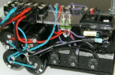
I have about finished the outboard supply for the Tex-X balanced Aleph type amp. I used a potted Bicron 1000 VA Torrid transformer that was a cosmetic reject for an famous audio designer friend. The primary has four winding that can be configured for 220, 115, or 100 volts AC. I put the 100 V windings in series and used the low voltage primary windings as secondaries for about +/- 15V DC. The Brige is made from 3 Dual high speed soft recovery diodes mounted on a heat sink. Caps are 4 X 33,000uF. Toggle switchs are for soft start. Earth ground is connented to signal ground by 50 amp bridge with jumper so that two diodes drops in series appear between ground for either polarity fault condition. Thsi is paralelled with a 150 ohm resistor. Wiring is silver plated OFC with teflon insulation. Solder is 4% silver reflowed with 36/64 Alpha since the transformer wiring is hard to heat for lead free solders. Another plexiglass strip will go over AC terminals. About a full days work.....
I have about finished the outboard supply for the Tex-X balanced Aleph type amp. I used a potted Bicron 1000 VA Torrid transformer that was a cosmetic reject for an famous audio designer friend. The primary has four winding that can be configured for 220, 115, or 100 volts AC. I put the 100 V windings in series and used the low voltage primary windings as secondaries for about +/- 15V DC. The Brige is made from 3 Dual high speed soft recovery diodes mounted on a heat sink. Caps are 4 X 33,000uF. Toggle switchs are for soft start. Earth ground is connented to signal ground by 50 amp bridge with jumper so that two diodes drops in series appear between ground for either polarity fault condition. Thsi is paralelled with a 150 ohm resistor. Wiring is silver plated OFC with teflon insulation. Solder is 4% silver reflowed with 36/64 Alpha since the transformer wiring is hard to heat for lead free solders. Another plexiglass strip will go over AC terminals. About a full days work.....
Attachments
Why using 3 double diodes and not 2? (looks like two of them you are used as singles). I didn't thought about ti,but to get lower voltage from a transformer you can actually connect primaries in series (as for 220V) and get lower secondaries. Any drawbacks to that (same power?). It may just save me $200.
HPotter,
I don't think there is a way to connect two pairs together to form a bridge because they have only three leads and they share a common cathode connection.
Greg
I don't think there is a way to connect two pairs together to form a bridge because they have only three leads and they share a common cathode connection.
Greg
I didn't notice. You can tell right away that I'm working only with bridges.😉 Quite an inconvenient package for audio though.
The Bridges of Haller County
The fullwave bridges could be done with a common anode and a common cathode dual but I was not that lucky. You could use four and parallel the diodes in each for more current capacity. Series connection has more winding resistance but is not a big deal for a transformer this big. Lower flux densisty too for series connection which can be an advantage for a torroid. Bypass caps will be next to output transistors with a 100,000uF per rail. 0.05ohm resistors between outboard supply and local caps will filter higher frequency components of ripple voltage.
H.H.
Joe,
Bummer.
What did you ever end up doing for the DC offset? Like I said, I'm open to suggestions.
My servo idea was common mode simply because I'm too lazy to build two circuits where one will do. One of the few cases where laziness might be an asset.
I've still got two or three ideas (one being what I think Ian was describing) but no idea how to implement them in the real world. I'm still thinking (Think, Pooh...<i>Think!</i>), but have not come up with a better way than the one I put in the schematic. Even though people are saying 'hair trigger' from simulations, once you get close, it gets fairly workable. It's not as liable to do the comparator <i>Snap!</i> response as you might think. Get within a couple of turns (remember--multiturn pot) and it just sorta drifts rather than snaps. Not bad at all. Rough it in. Keep an eye on it as it warms up, then fine tune it when it's hot. Done. Takes about 30 minutes to an hour worth of cooking time with the heatsinks I've got here.
There'll be something obvious staring me in the face if I can only get some sleep...
Perhaps you and Ian can think of something. Naptime for this li'l bear.
Grey
heX amp w/ resistors to ground
Ian, regarding your concern about using resistors-to-ground with a headphone X amp -- I think you'll be able to scale the resistor values up in proportion as you scale back the bias current, giving roughly the same percentage efficiency loss as with a larger amp.
My theory is that the resistors-to-ground work by translating changes in absolute DC offset voltage into changes in idle current through each of the Aleph current sources. When the Aleph control loops act to correct these changes, they are in effect acting as servos to cancel out the DC offset voltage.
If this is correct, then the load resistor value required to keep the DC offset stable is inversely proportional to idle current. So, if we find experimentally that 30 ohms is needed to stabilize DC offset with an idle current of 2-3A per side, you should only need about 300 ohms to stabilize a circuit idling at 1/10 of that current.
heX amp
Attached are two schematics that will hopefully better illustrate what I was talking about in my previous post. Don’t pay too much attention to the actual components depicted, particularly the mosfets as these are simply those for which I have Spice models. Note too that the schematics are simplified to cater for the restrictions of the program– mine is only a student version. Hopefully these things will not detract too much from illustrating the principle involved. Apologies for any inaccuracies; time is tight as I am squeezing this in before going away on business for a few days.
Grey, I still have a few questions but most will have to wait until I have more time. I would like to say though that it was not my intention to remove the need for manual adjustment of the current source – I just wanted to make it less sensitive and prone to drift. I take your point about it not being a significant issue in practice but I remain a little concerned since positive feedback appears to be involved. My primary goal was to simply(!) compensate for the positive feedback.
Joe, I’m not sure about your theory regarding the resistors-to-ground, mainly because the same behaviour is exhibited when using regular current sources for the output rather than the Aleph ones. That said, I will be pleasantly surprised if it turns out that you are right regarding scaling with bias. My own theory is that the resistors effectively reduce the gain of the output mostfets, hence reducing the amount of postive feedback (for signals applied to the input mosfet’s sources). Then again I could easily be wrong.
Attachments
Ian,
Your "Servo" is virtually the same as what I did.
"CM Feedback" is a cool idea, but I'm not sure it will work. The current through the third MOSFET (M9) won't be the same as the two MOSFETs comprising the differential, so the Vgs won't be the same. If the Vgs isn't the same, then you're back to having to contrive an adjustment of some sort to reset the thing to the right voltage. If you don't, you're going to lock in something like, say, .25V DC offset as your baseline for the output.
I had looked at the idea of using a Zener instead of the Vgs of a MOSFET to accomplish the same thing you're trying to do here, but again...there was that adjustment to zero the thing out.
I like the MOSFET Vgs idea--it's more elegant than the Zener idea I had--but I just can't convince myself that you'll get 0VDC at the output, unless you can get the same current through the feedback MOSFET as the two in the differential.
Any ideas along those lines?
I've got a couple of other observations, but I want more time to think about them. They may be okay as-is, or there may be an easy fix. I'll try to ponder on this one during slow times this evening.
Grey
EDIT: Oh, regarding adjustment...if we're going to rejigger the thing, let's get rid of the adjustments entirely. I'd prefer not to have to fiddle with the circuit once I build it. However, as I said, in practice the circuit isn't anywhere near as difficult to adjust as people seem to feel from looking at simulations.
Grey,
there has been a lot of talk about DC offset...is that really a problem or are we just in 'paranoia mode'? Do the 30 ohm resistors really work or what? Are you getting the feeling that Nelson went through all this tried the resistors but eventually came up with something better for the commercial version?
I guess the final pcb layout will be on hold until this issue is sorted out.
grataku,
There are people who are truly concerned about being struck by lightning. Yes, it happens, but it's not something I intend to spend a lot of time fretting about. Others have different priorities.
I haven't simulated the circuit. I built it, instead. It would seem that the simulations have little curly whisps of smoke coming off of them from the way some people are reacting. Enough ink has been spilled elsewhere about the differences between simulations and reality that I feel no need to reiterate all that here. Suffice it to say that:
1) There probably is a better way to adjust the DC. I've still got an idea or two that I'm going to try if I can figure out how to do them. They may work, they may not. Most of the ideas I started with didn't pan out. Such is life. I believe I've already told this story, but I'll repeat it here--I once had a "customer" who was always on the verge of buying something, but never did. He was always reading the magazines to see what was coming out. As soon as he'd read that company X had a new receiver, he'd back off from plans to buy a model from company Y. He was always in a dither of indecision.
If we are not to end up like my erstwhile customer (I believe they call them 'clients' these days...gag...), there comes a time to act. I intend to build a circuit so that I can listen to music. If a workable modification comes along...great! The transformer and heatsinks (i.e. the most expensive parts) won't be the parts modified. I can even re-use the output devices (the next most expensive parts). This is why they invented solder-suckers.
2) I'm working on a PC board, but am having difficulty getting it onto a single-sided board given the rules that I abide by when making a board. (No connections to the middle of the board, no jumpers, etc.) The obvious solution is a double-sided board, but given the number of people who are PCB-challenged around here, you could probably count on one hand the number of folks who'd follow through with a double-sided board. Most don't even attempt a single-sided board. Point-to-point wiring will work, of course, but by definition, the people who want to do P-T-P don't need a board. Double-sided boards don't scare me--done a bunch of them--but I'd still like to come up with a single-sided implementation, just so more people could build the circuit.
3) I imagine Nelson has something up his sleeve for the commercial version, but I'm not privy to the secrets of Pass Labs. I'm Just Me.
Grey
- Home
- Amplifiers
- Pass Labs
- The Aleph-X