Front End current sources
This shows the frount end current sources for the Tex-X balanced Aleph-X type amp. The voltage reference is an LM329 with a voltage of 6.9 volts. This is biased by a couple of J501 current reference fets and series resistors from the negative 15v rail minimize the capacitance. Calculated rejection of audio band supply noise is about a factor of a few million. A typical zener and resistor combination gives a rejection of about a thousand fold for supply noise. The voltage noise for the LM 329 is also much lower than for a zener. I used Zetex ZVP3310s for the mosfets instead of the IRF 9910s for much lower capacitance and twice the simulated output impedance. A series 10 ohm resistor for each current source will also help to isolate any RF interactions with the front end IRF9610 diff pairs. Bias value is very stable after the mosfets warm up. A Rifa 100nF cap across the LM329 insures RF stability and filters any RF noise from supplies.
This shows the frount end current sources for the Tex-X balanced Aleph-X type amp. The voltage reference is an LM329 with a voltage of 6.9 volts. This is biased by a couple of J501 current reference fets and series resistors from the negative 15v rail minimize the capacitance. Calculated rejection of audio band supply noise is about a factor of a few million. A typical zener and resistor combination gives a rejection of about a thousand fold for supply noise. The voltage noise for the LM 329 is also much lower than for a zener. I used Zetex ZVP3310s for the mosfets instead of the IRF 9910s for much lower capacitance and twice the simulated output impedance. A series 10 ohm resistor for each current source will also help to isolate any RF interactions with the front end IRF9610 diff pairs. Bias value is very stable after the mosfets warm up. A Rifa 100nF cap across the LM329 insures RF stability and filters any RF noise from supplies.

Re: bridged design also requires more output current anyway
Exactly! In a single ended design, the amp might swing 16V into an 8ohm load, sourcing and sinking around 2Amps. However, in a bridged design where both sides swing 8V into that same load giving the same total voltage swing, one 1/2 is sourcing the full 2amps and the other half is sinking it. So for a given voltage swing it appears that each side of the amp is driving half the nominal load. That's why we've just had all this discussion about using lower voltage rails but higher bias because current draw thru a given side of the amp at any given time is twice that of it's single ended eqivalent. For a given voltage swing the output current requirements of a single side of the balanced amp is doubled relative to a single ended amp outputing the same total voltage swing.
HarryHaller said:What!!!!??? Assuming we are talking about the same votage swing into the same load impedance, I am afraid I don't follow your reasoning.
Exactly! In a single ended design, the amp might swing 16V into an 8ohm load, sourcing and sinking around 2Amps. However, in a bridged design where both sides swing 8V into that same load giving the same total voltage swing, one 1/2 is sourcing the full 2amps and the other half is sinking it. So for a given voltage swing it appears that each side of the amp is driving half the nominal load. That's why we've just had all this discussion about using lower voltage rails but higher bias because current draw thru a given side of the amp at any given time is twice that of it's single ended eqivalent. For a given voltage swing the output current requirements of a single side of the balanced amp is doubled relative to a single ended amp outputing the same total voltage swing.
Grey
Apologies for the long post…
-- Sensitivity to driver diff pair tail current
Having read your comments and thought about it some more, I think I was probably mistaken regarding my positive feedback assertion. I originally thought that common mode DC at the output would result in a regenerative effect when compared with the voltage at the Sources of the drivers. Unfortunately, it seems that I forgot that this point is effectively floating… Hence the absolute DC offset problem is simply(?) a matter of setting the correct current. IMHO the reason this value is sensitive appears to be due to the open loop gain of the circuit since, as you point out, the driver is insensitive to common mode output voltage. I now firmly believe that the output resistors to ground act to reduce the open loop gain of the output stage and hence reduce the sensitivity to the value of driver current. Having played around with a few values, it looks like there is a (inverse) linear ratio of resistor value to sensitivity. For example, a pair of 1K resistors to ground results in an output voltage to input current ratio of 150V/mA, whilst 30R reduces this to a more manageable 4.4V/mA.
-- A better way?
In truth I’m not sure there is a better way, only a myriad of different ways. However, I’m still not particularly happy about dissipating power in the output to ground resistors, nor particularly keen on throwing away gain in this fashion. If gain needs to be reduced, I would rather it were done with (local) negative feedback so as to benefit from the effect. But I also see that this is not easy to accomplish, at least around the output stage. This brings me back to the idea of trying to control the common mode behaviour of the circuit by using more global feedback. I’ve experimented with the two resistors from outputs to driver sources arrangement and believe this can be made to work. A pair of 2K resistors has much the same effect on driver current sensitivity as the 30R resistors to ground but with greatly reduced power wastage. However, I don’t think that this topology can be used without some form of adjustment – there isn’t sufficient gain.
-- Vgs matching
Regarding my use of a MOSFET for Vgs compensation with the common mode feedback resistors. I take your point about not being able to match the value due to the difference in current between driver currents and compensation voltage source. In fact I don’t think the idea is really practical, at least not as I had it. The current in the MOSFET acting as a voltage source is far too low (tens of microamps) and varies with a consequent effect on Vgs. In theory this could be rectified by the addition of another current source between the junction of R87 and R89 (as per my last post) and the negative power supply. However, in practice there would be a similar problem of determining this current accurately enough and it all gets too complicated. Fortunately I don’t believe that a voltage source is required. The required voltage drop may be achieved simply by the effect of the current flowing through these resistors. I’ve tried this on the simulator and it seems to work. Still need the tail current adjuster though.
-- Servo
I’m still not sure about this. I am confident that it will work in terms of controlling the absolute DC voltage at the output but I am not so sure about the effects on sound quality. Having so much gain (even if low by normal servo standards) in the common mode loop is unlikely to be a good thing. My concern is that any imbalance in the two halves of the bridge (e.g. distortion components) will result in a significant common mode component. Now I appreciate that the speaker will not notice, but I would rather not have any additional spurious signal to interact with the desired one. Perhaps a more conventional servo is required, e.g. make it work only at low frequency?
-- Input Z
I’m not convinced by your assertion that R19 and 29 set the input Z (but of course I could easily be wrong). Aren’t the gates of the input MOSFETs effectively a virtual ground by virtue of the feedback? If so, then the input Z will be determined by R18 and 28, i.e. 10K single ended and 20K balanced in the stock design. I’m pretty sure that these resistors could be omitted completely though there may be other reasons why it is not desirable to do so. I notice that Sonny is talking about reducing these resistors to 3.3K or so, in which case I hope his preamp doesn’t mind the lower impedance. Personally I don’t think the frequency response is an issue with your original values.
-- Theory versus Practice
I think I have probably done this one to death on the theory side, though I would still like to properly understand the operation of this fascinating circuit. As Harry says, “analysis is paralysis” and I believe this to be at least partly true. Time I think to order some components and begin building! I think 1 will initially go for a headphone version as previously discussed, with output current of 100mA per side and probably using J109 front end, always assuming I can find some of the latter. I will start with the basic circuit (but I will have to use larger output resistors to ground at these currents) and if I am able to stabilize it, perform some listening tests (headphones are pretty good analytical instruments). I will then try the common-mode resistors and finally the servo, with and without low pass filter. I’ll report back to the forum on my subjective findings.
-- Thanks
Grey, thanks once again for sharing this with us and of course we must not forget Nelson Pass who made all this possible. I look forward to hearing your thoughts and of course anyone else’s view on how this thing sounds. I am also very interested in your preamp ideas, particularly the bit about correction without feedback. And of course, I would just love to be let in on the secret of Wayne’s great attenuator, but I guess that is the subject of another thread.
The resistors to ground are only part of the solution,
but keep in mind that the absolute DC offset of the
design has only nominal importance - it is the differential
that the speaker sees, and this is quite good. Absolute
offset less than a volt is quite acceptable.
The secret of Wayne's attenuator is an extremely clever
use of bipolar devices to shunt signal to ground. It is
extremely linear, quiet, and handles much more voltage
than prior art. Surveying the commercial offerings at the
time of its development, we found that it was better by
a factor of about 10 in each of these three criteria.
Maybe someday the patent office will get finished with all
the internet business model applications and get back to
real inventions, and then the circuit will be public.
Nelson,
Thanks for making time to respond to some of my questions. On the question of the resistors to ground being only part of the solution – are you saying that I am overlooking the significance of something else already in the existing circuit or that an important element is missing from the circuit? Sorry if I am a bit slow…
Here’s to the patent office getting its act together
🙂
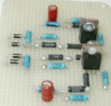
Tex-X front end
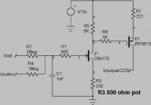
Front end for Tex-X amp. It is wired for single end input with output cap coupled preamp. The other input is coupled to ground with 33uF BlackGate cap paralelled with 100K resistor. All resistors are non magnetic Corning RN60D. Back to back 5 volt zeners at input to prevent gate damage. I did not tie to gates directly to avoid stray capacitance at input feedback junction. the sources are connected to current source board to decouple for output capactance of current sources. Mosfets are mounted back to back with Mica washer, thermal grease and nylon screw for thermal tracking for low offset drift. Gain is abount unity at DC for further offset control. Hope to have running in a week or two if no fireworks before July 4th.
Front end for Tex-X amp. It is wired for single end input with output cap coupled preamp. The other input is coupled to ground with 33uF BlackGate cap paralelled with 100K resistor. All resistors are non magnetic Corning RN60D. Back to back 5 volt zeners at input to prevent gate damage. I did not tie to gates directly to avoid stray capacitance at input feedback junction. the sources are connected to current source board to decouple for output capactance of current sources. Mosfets are mounted back to back with Mica washer, thermal grease and nylon screw for thermal tracking for low offset drift. Gain is abount unity at DC for further offset control. Hope to have running in a week or two if no fireworks before July 4th.
Attachments
Ian, you are not particularly missing anything, but there
is a secret trick I invented for the X circuit which additionally
stabilizes the absolute voltage. You can get by without it,
but I will give a prize to the first guy who thinks of it.
is a secret trick I invented for the X circuit which additionally
stabilizes the absolute voltage. You can get by without it,
but I will give a prize to the first guy who thinks of it.
Harry,
You used non magnetic resistors and plastic screws to put mosfets back to back. I'm just curious if the nuts are non magnetic as well?😎
You used non magnetic resistors and plastic screws to put mosfets back to back. I'm just curious if the nuts are non magnetic as well?😎
From Petter's schematic of the X, it appears
that the feedback is taken from a point that
is "floating" between the output pairs.
(between R6 & R7 and R36 & R37)
I don't see how a DC offset could find it's way
back into the circuit.
This kind of thinking makes my head hurt...😕
that the feedback is taken from a point that
is "floating" between the output pairs.
(between R6 & R7 and R36 & R37)
I don't see how a DC offset could find it's way
back into the circuit.
This kind of thinking makes my head hurt...😕
plastic screws
For the electrical insulation and ease in cutting to length. You could use heatsink mounting kit with nylon shoulder washer instead. I am fairly sure that my nuts are not magnetic.
H.H.
For the electrical insulation and ease in cutting to length. You could use heatsink mounting kit with nylon shoulder washer instead. I am fairly sure that my nuts are not magnetic.
H.H.
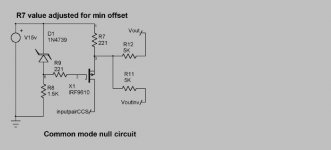
Stabalizes the output voltage
Harry, your servo is similar to the idea that I posted a short time back, albeit a little simpler. Personally, I think Nelson had something more innovative (and probably simpler) in mind 🙂
Harry, your servo is similar to the idea that I posted a short time back, albeit a little simpler. Personally, I think Nelson had something more innovative (and probably simpler) in mind 🙂
Magnetism
Hi Harry, are modern nylon screws long term reliable, and able to pull down really tight ?
I have fixed gear using nylon screws where the threaded part, or the head has broken whilst in service, so have always avoided them.
BTW I'm glad that your nuts are non-magnetic.
Regards, Eric.
Hi Harry, are modern nylon screws long term reliable, and able to pull down really tight ?
I have fixed gear using nylon screws where the threaded part, or the head has broken whilst in service, so have always avoided them.
BTW I'm glad that your nuts are non-magnetic.
Regards, Eric.
probably simpler......
I'm sorry that one cap, one jfet, and a few resistors is not simple
or innovative enough for you. This mosfet current source is already there by the way and does not count for extra parts. Speculation on Mr. Pass's approach is easy, let's see some more guesses on how to do this.
H.H.
I'm sorry that one cap, one jfet, and a few resistors is not simple
or innovative enough for you. This mosfet current source is already there by the way and does not count for extra parts. Speculation on Mr. Pass's approach is easy, let's see some more guesses on how to do this.
H.H.
Probably simpler...
Sorry, didn't mean to sound disparaging... I admit that your implementation is more elagant than mine. All I was saying is that it is still a servo and somehow I had the impression that Nelson's "trick" was something different. I'll still thinking about what this might be...
Sorry, didn't mean to sound disparaging... I admit that your implementation is more elagant than mine. All I was saying is that it is still a servo and somehow I had the impression that Nelson's "trick" was something different. I'll still thinking about what this might be...
Simplest?
Clever idea, I hadn't thought to connect the common mode feedback to the Source of the current source (I previously posted a similar idea but to the Drain). It certainlly qualifies as simple. As to whether it is along the same lines that Nelson had in mind I couldn't say. Perhaps you should ask Nelson whether your idea qualifies for his prize?
I'll try this out on the simulator later... And yes, I know many folks hate simulations but I find it is a good place to begin. Just as long as it doesn't become an end in itself.
- Home
- Amplifiers
- Pass Labs
- The Aleph-X