I thought that the capacitance was the somewhat critical element in the sound perfo
It can be depending on the design. The most important factor is transconductance. Higher transconductance comes with higher capacitance generally speaking. I believe the lower voltage parts generally have higher transconductance for a given bias current if I am not mistaken. Another factor is bias current. The higher the bias current the higher the transconductance. Lowering the supply voltage allows one to bias the mosfet harder for a given power dissapation. Everyone see why balanced ouput amp with lower rails looks like an attractive approach? Lower power supply rail voltages will let one use lower voltage parts with thier better transconductance specs
H.H.
And lower rails also means lower rated caps for power supply (one of the big costs). I think 25 V caps are cheaper than 63, 75 or 100 V caps in most parts of the world. I myself just got a good place to use a bunch of RIFA caps with 40 V rating I had in the box.
/UrSv
/UrSv
Thanks to all for the information!
I've been trying to find a stash of 040's and so far have only been able to locate small numbers of them...
Does anyone have a datasheet for the 040's that they would be willing to post? I've been unable to find a copy...
I've also contacted IR about the minimum quantity required for a production run. They consider it an obsolete part but I figured that it couldn't hurt to ask...
Lastly, in conversation with IR, they just shipped a substantial quantity of the 044's to Avnet... The last order shipped was not the "N" version of the die... Avnet wants $1.1425 each for 1 - 25, $1.1225 for 26 - 50, and for 125 or more $1.07 each. They have 1300 in stock...
Thanks again for the help!
Steve
Everyone see why balanced ouput amp with lower rails looks like an attractive approach? Lower power supply rail voltages will let one use lower voltage parts with thier better transconductance specs
And the lightbulb comes on... Thanks for summing it up so nicely, HH!
This design is so completely synergetic! It would take a master like Nelson to come up with something so simple, yet so effective in so many different ways!
I decided to scrap my plans for a pair of A75's and build a pair of these. Is there going to be a problem with the front end, as far as driving extra pairs of output devices? Will the extra capacitance limit the bandwidth too much? I would like to be able to drive a load of anywhere from 3.2-8 ohms to 70 watts. I come up with needing a 35V p-p swing into 8 ohms, and a 4.7A peak current into 3.2 ohms. (correct me if I'm wrong here)
So, how would I go about figuring out the rails, and bias? I apologize, but I don't have any experience with balanced or Aleph designs.
Steve
Datasheets for 044 and 240 for those who are interested...
Still searching for the 040 sheet...
http://www.irf.com/product-info/datasheets/data/irfp044.pdf
http://www.irf.com/product-info/datasheets/data/irfp240.pdf
At what point will the device input capacitance begin to be a factor? I'm looking at doubling the number of output devices on the Aleph 1.2 backend (closer to the X600) and I'm curious if this will create problems? Also, will it be necessary to double the number of drivers?
Opinions?
Yes, I know some may think this is just a waste of $$. On the other hand, I think improved damping, and lower die temp therefore being able to run more bias current might be worth it but I don't want to do it if it'll sacrifice the high-end performance...
Thoughts?
Thanks,
Steve
SteveG
See Grey's posts here (two of them regarding this topic):
http://www.diyaudio.com/forums/showthread.php?s=&threadid=3748&perpage=15&pagenumber=8
I think you'll find what you need...
Steve
See Grey's posts here (two of them regarding this topic):
http://www.diyaudio.com/forums/showthread.php?s=&threadid=3748&perpage=15&pagenumber=8
I think you'll find what you need...
Steve
Look what I found....
This looks very interesting to me but I'm not clear on how the convert between Gfs and Yfs transconductance figures...
IRFP044
Vdss - 60V
Id - 57A
Gfs - 17min
Ciss (input capacitance) - 2500 typ
Rds - .028 ohm
http://www.irf.com/product-info/datasheets/data/irfp044.pdf
Toshiba 2SK3129
Vdss - 50V
Id - 60A
Yfs - 40 min, 70 typ
Ciss (input capacitance) - 3700 typ
Rds - 5.5 meg ohm
http://www.toshiba.com/taec/components/Datasheet/2sk3129ds.pdf
Has anyone tried these Toshiba's? The only thing that concerns me is the turnoff time - they are faster on the rise but slower on the off... Are they suitable for our application? How do they sound?
Thoughts?
Thanks,
Steve
Mosfet current source biasing
According to Mr. Rollins
"To calculate the Source resistors, divide the total bias current in half to get the amount for each side. Since I'm assuming one pair of devices per side (four total for the channel), we'll end up biasing the pair at 1.9375A (3.875A/2 sides). We'll set the voltage at .5V across the Source resistors (don't forget that you can adjust this a bit with the pots). From here, it's a simple Ohm's Law calculation: .5V/1.9375A= .258 ohms."
According to Nelson Pass in The Zen Variations - Part 2
"When current begins flowing through the MOSFET, voltage is developed across .33 ohm resistor R1 which will equal .33 volts for each amp of current flow. Q3, a PNP transistor, is set up so that it sees this voltage across R1. Bipolar transistors have a characteristic where they will begin to conduct when their Base to
Emitter voltage approaches .66 volts or so, and when the voltage across R1 gets to about .66 volts, Q3 begins to conduct. By comparison, MOSFETS begin conducting between 2 and 5 volts, and are quite variable between types and parts which is why we use a Bipolar device here. But I digress… When Q3 begins to conduct, it limits the Gate voltage of Q2, and this forms a little feedback mechanism which limits the voltage across R1 at about .66 volts. R6, R7, and C3 are there to help make this arrangement stable and reliable, and we could possibly omit these, but we won't. If the voltage across R1 is a stable and constant .66 volts, then the current through R1 is a stable and constant 2 amps, and that means the current through Q2 is a stable and constant 2 amps, and so we have a 2 amp stable and
constant current source."
Take your pick.
H.H.
Tranconductance
Transconductance is the change in drain current for a given change in gate to source voltage. It is given in units of Seimens or amps per volt. Rds is in milliohms and not relevent to the disscussion since it is measured when the Fet is turned all the way on a switching application.
To compare the transconductance of the two mosfets they would have to be measured at the bias current levels used in an amplifier. This would be in the region of 0.25 to 2 amps in most cases and would be in the region of 1 to 10 S (Seimens) for most power mosfets and depends heavily on the bias current. The numbers given in the data sheets are measured at 34 and 40 amps are not representative on the numbers at bias currents of 0.25 to 2 amps. As in all advertising it is helpful to read the fine print. In a data sheet there is lot of it..... and graphs too!
The Toshiba looks like a beast but I don't know what it would sound like but I would like to find out since they make some great transistors.
H.H.
The Aleph circuit Nelson used as the basis for the Zen variations article isn't quite the same as the one he used in the production amplifiers. Amongst other things, it lacks R11 and R33 (nomenclature from the Aleph-X schematic), and of course, V1 and V3 (there were no adjustments of any kind in the production Alephs). This leads to the difference between the Zen article saying .66V across the Source resistor, and my choice to remain with the nominal .5V that is shown in the Aleph schematics.
In fact, you can leave out R11, R33, V1, and V3 if you like. This is equivalent to setting R11 and R33 to infinite resistance, and will get you up towards the .66V level. The lower the effective resistance through those legs, the lower the voltage across the Source resistors, and the lower the bias current. There's nothing magic about .5V--you're free to set it where you like.
Someone (Sonny?) was already inquiring about using an ordinary current source as per the original Zen. Leaving out the resistance above the base on the MPSA18s would provide yet another variation. I was driving in to work one day thinking about variations on the Aleph-X circuit and came up with, I think, six even while driving in heavy traffic. Nelson has said that he's come up with something like 200 variations.
It's enough to make you dizzy.
Harry,
I scribbled some notes this afternoon, we'll see if I can read them (my handwriting gets worse when I'm in a hurry).
--Cold bias starts at about 3.6A total for the amp.
--The bias increases over about the first twenty or thirty minutes (this will depend in part on thermal conditions) to approximately 4.5A, which is in close accordance with what you'd calculate from the schematic. .5V/.22 ohms= 2.27A per side or 4.54A draw for the entire amp. (Bear in mind that the Source resistors I've got in the circuit right now are 5% ceramic, so that introduces some variance, and I still haven't gone back and fine-tuned the bias, etc...)
--Output increases as the amp warms up, but it will swing on the order of 17.5Vrms across 8 ohms, and would probably have done a little better if I had had sufficient time to let it warm up longer. This works out to a little over 38Wrms.
--The efficiency, in terms of current in/current out approaches 50%...I calculated it at something like 48%, as I recall, which ain't bad at all for a single-ended class A amplifier.
--Gross clipping, meaning overdriving the amp until the output resembles a square wave, only increased the AC on the rail by something like 5 or 10mV. All in all, a pretty well behaved critter. (8 ohm load)
My personal feeling is that anyone who clips an amp is a silly goose and needs their audiophile license revoked. Folks should learn the sound of clipping and either turn the volume down or build a bigger amp.
As though we didn't already want bigger ones anyway...
--You were asking if the pots (V1 & V3) could be eliminated. Yes. As I said before, these can be replaced with fixed resistors. I'm using matched IRF044s (others may choose not to, which is one reason I put the pots in), but am having fun playing with the bias. I'm of two minds as to whether to use fixed resistors: on one hand pots are bad, on the other hand the ability to set bias to arbitrary levels (possibly to include a standby mode?) is kinda nifty. Today, I'm leaning towards a fixed resistor solution...tomorrow, I may lean towards pots. Decisions, decisions, decisions...
At any rate, and particularly with matched devices, the pots are no more necessary than they would be in a 'normal' Aleph. They're just there for fun. Use 'em or not as suits your mood.
Steve & Steve,
Nelson says that going beyond 12 devices tends to require reconsideration of the front end. Perhaps a follower is in order?
There's no reason that you couldn't hang a half-dozen pairs of devices off each side (think bridged Aleph 2s), which would give you something approaching 400W output. Unless, of course, nothing will do but to build a pair of back-to-back Aleph 1.2s which, at 800W/8 ohms, should be enough for most mere mortals.
If anyone does a head-to-head comparision between IRF and Toshiba devices, please report back. I'd be interested in hearing about differences.
Grey
Ah, that's a much better price than Digikey, Steve. You just saved me 30 bucks, thanks.
Another quick unrelated question of mine - what voltage rating of power capacitor is required for a given rail voltage? For example with 20V rails would a 30V cap be adequate? I'm also curious as to whether it's better to use a single very large capacitor versus many smaller ones. I apologize if these questions have been asked before, I'm spending all my time reading about heatsinks. 🙂
I like that this amp is over 50% efficient at maximum output due to the current source design (or does this not work out in reality?) Going by Grey's rules of thumb I'll be dissipating 250W and outputting 150W. Interesting. The low rail voltage requirement IMO is a double-edged sword for those of us driving low impedance loads requiring high current and hence uncommon transformers.
Bias
Thanks for your very concise report. I think it will be very useful to all. I too have thought about source followers biased for 10 or 20 mA with a resistor from source to ground to drive the output mosfets. A 2SK215, IRF510, or a Zetex ZVN060 would be excellent canidates for this. This would also alow the use of larger drain load resistors for the front end and more open loop gain and even the use of a J109 jfet pair for the front end ( maybe ever with some source degeneration which jfets love) but we will save that for version five or six. First someone needs to finish the original design. I am working towards that end but it is still a more involved project than one might think.
H.H.
Tex-X status
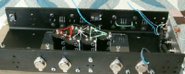
Tex-X amp progress report. Picture shows surplus U channel from 350 watt mono block amp for mounting transistors to surplus heat sink. IT was already drilled for T03s and I drilled a few more holes. Caps for +/- 15 volt supply mounted on piece of plexiglass to insulate from heatsink temperature and allow easy removal. Vishay 0.25 source resistors in TO3 cans are mounted on outside of the U channel. The IRFP 150s and Caddock 0.05 ohm resistors are mounted on inside of U channel. I wiill build front end, front end current sources, and Ouput current source ZTX bipolar circuits on small vector boards that can be removed for test, mods, and parts update. This also makes things a little more rugged mechanically. I hope this gives some ideas for point to point wiring and layout for short signal path while still allowing easy access for soldering and testing. Will update as I make more progress. Planning the layout carfully will save alot of labor and headaches later.
Tex-X amp progress report. Picture shows surplus U channel from 350 watt mono block amp for mounting transistors to surplus heat sink. IT was already drilled for T03s and I drilled a few more holes. Caps for +/- 15 volt supply mounted on piece of plexiglass to insulate from heatsink temperature and allow easy removal. Vishay 0.25 source resistors in TO3 cans are mounted on outside of the U channel. The IRFP 150s and Caddock 0.05 ohm resistors are mounted on inside of U channel. I wiill build front end, front end current sources, and Ouput current source ZTX bipolar circuits on small vector boards that can be removed for test, mods, and parts update. This also makes things a little more rugged mechanically. I hope this gives some ideas for point to point wiring and layout for short signal path while still allowing easy access for soldering and testing. Will update as I make more progress. Planning the layout carfully will save alot of labor and headaches later.
Attachments
Here's what I'm thinking about for my X...
Use the Volksamp 30 output stage and basic front end (with Greys modifications of course). From what I can tell, this should be good for about 150 Watts into 4 ohms, or 120 into 8 ohms (I take it that the Volksamps aren't biased for full current 4 ohm operation at the same voltage level).
Any suggestions or warnings? This really makes for a comparatively cheap amp when you consider the 25V rails allow cheaper filter caps, it only has 12 output Mosfets per channel, etc. I am speaking in comparison to the A75. I will try to come up with a schematic soon for everyone to pick at, if they are willing.
Steve
Grey
First off I would like to say a very big thank you for sharing your design with us - this is the sort of thing that makes this forum the best. I'm writing as I have some concerns and questions regarding the design that do not seem to have been addressed yet. Please take these in the spirit that they are intended, as a way of exploring and hopefully moving forward – they are explicitly not intended as criticism.
My main concern is with the design’s extreme sensitivity to the value of the current for the input differential. I admit to considerable trepidation at building something like this, mainly because of the likely drift (then again I will probably go ahead and try it anyway). By my reckoning this sensitivity is due to positive common mode feedback, hence the voltage at the output tends to one or other power rail if the current isn’t spot on. I see from some quick simulations that the resistors from output to ground reduce the problem but they do not banish the underlying problem. I admit that I am curious as to why the resistors have this effect. Is it simply that they reduce the gain of the output devices?
If it is at all possible, I would like to find a better solution to the absolute DC issue, particularly as I would like to build a low power version where the resistors would dissipate a disproportionate amount of the total power. You mentioned the use of a servo in one of your early posts, but I wonder if it is not possible to do better? I’m not really a big fan of servos. It occurs to me that it may be possible to add some common-mode feedback to alleviate the sensitivity and, as a by-product, improve the CMRR at the same time. I appreciate that the design is intended as a differential amplifier and that SuSy tends to increase the common mode component, but if this could be addressed without compromising the differential performance, wouldn’t this be a bonus?
I’ll try and share my thoughts – no doubt readers of the forum will tear my ideas to pieces, but then that is how we learn and progress. The most basic (read crude) implementation would be to connect two equal value resistors (about 10k is a good value) from the outputs to Q6 drain (in practice a voltage source would also be required to compensate for the Vgs of the input mosfets). This effectively provides common-mode feedback in opposite phase to the common-mode input. In theory, this should not compromise differential performance as the feedback voltage is common-mode and is also applied common-mode to the input. Of course, imperfections in the balance between the two halves of the bridge will cause the action to be less than perfect in practice.
An improved (to my mind) implementation would be to modulate the current source with the common-mode signal from a pair of resistors connected to the outputs. I’ve simulated a simple discrete diff pair arrangement to do this (schematic available if anyone would like) and the result looks quite promising. Any merit in these ideas or am I simply messing with something that already works just fine in practice?
Finally a small question: how did you determine the values of R19 and R29? Are they essentially arbitrary? Lower values appear to improve performance but also tend to result in reduced high frequency response.
I’d like to build a variation of this circuit as a high impedance headphone amplifier (my headphones are suitable for bridge topology), maybe using J109 dual JFET front end and 100mA output current sources. However, I would like to be sure that absolute DC offset is not going to be a problem first (particularly with larger values of output resistor to ground).
Keep up the great work!
Ian.
common mode feedback
Ian, you may like to know that the idea you describe above was used -- I presume successfully -- in at least one commercial predecessor to this design. I recently snared a schematic for the Hadley 622, the earliest example I've found of a four-quadrant solid-state balanced bridge power amplifier (ca 1965). Its balanced quasi-complementary output stage is driven from both sides of an NPN differential pair biased by an NPN current source. Common mode feedback is taken from the output nodes back to the NPN current source through an adjustable resistive network.
I hope this gives you whatever encouragement you may need to follow your own nose in this regard and report your findings. To complement what you've said above, this is ALSO how we all learn here . . .
HE(adphone)X amp
Man are you on the right track. 15 volts rails and a J109 diff amp front end would be cool. IRF510s or 610s outputs and IRF9610 current sources for the outputs would work. I would use the output 2 resistor to ground scheme as you really need to see a common mode imedance to ground for decent offset ( particularly common mode offset) Power savings with the outputs biased this hard will be not worth notice. You can do a common mode servo also with another J109 as a low gain servo. This is a little to involved to describe but maybe a schematic later. Go for it!
H.H.
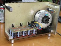
All my heatsinks, except the ones I used for flagship A75, come from surplus. Those for instance I bought 5 years ago and had the chance to use them just now. I didn't know I will have much use out of them but due to clever idea it looks like it's going to be the cutest amp I ever built that's why I give it a priority over GAX. How do you mount your caps to plexiglass: with silicon? As you see on my previous picture I used red RTV used on aircraft engines.
Attachments

- Home
- Amplifiers
- Pass Labs
- The Aleph-X