The Stub geometry was dependent on the speaker driver cone & baffle cut out dimensions - hence 'Cone correction'
What driver would you be using I will try to find the info on how to calculate & repost it .
This is one reason why there is no generic stub solution - What would suit one driver might kill another.
Braces look too minimal - Could be left solid or cut out maybe less if you want the weight loss.
First 3 corner reflectors are probably optional - Might just work better without = More internal volume.
Thanks for the reply! Yeah i did think that but thanks for clarifying. The drivers i have are the BMS 18N862. Thanks so much for any help mate!
For the braces, i'll make them more solid and slightly larger and take out the 3 corner reflectors 👍
For the braces, i'll make them more solid and slightly larger and take out the 3 corner reflectors 👍
Could not find the previous Posts so looked into my Archive Files.
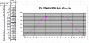
These examples relate to the B&C 18SW115, and it is a bit complicated to explain.🤓
Firstly I modelled the volume of air inside the cone - and the baffle cut out.

Next I sliced through the model at 2cm intervals and measured the cross sectional area This example is through the centre position.

I plotted the results in a spreadsheet and divided the area by the internal width of the speaker to get a height dimension.

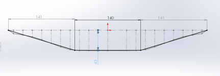
Surprisingly enough the centre of the plot becomes almost a flat line. Plotted the result in CAD.

And added a simplified 3 line equivalent by eye.

This line then replaces the speaker baflle when setting out the cross sectional area of the Speaker Sim and totally accounts for the volume of the cone and baffle - 'Cone Correction!'

Note the 48mm X 140 correction line & the 86mm that represents S2, so Overall compression at S2 is directly comparable with the compression ratio as reported in Hornresp.
Note I decided to do away with the extra panel / restriction that narrowed down S1 which results in a 'Stub' at S1- But in hornresp this causes a loss of HF extension, and also really puts the sim into Akabak territory.
No I never built a TH18 like this but did build a comparable smaller version that I use.
These examples relate to the B&C 18SW115, and it is a bit complicated to explain.🤓
Firstly I modelled the volume of air inside the cone - and the baffle cut out.
Next I sliced through the model at 2cm intervals and measured the cross sectional area This example is through the centre position.
I plotted the results in a spreadsheet and divided the area by the internal width of the speaker to get a height dimension.
Surprisingly enough the centre of the plot becomes almost a flat line. Plotted the result in CAD.
And added a simplified 3 line equivalent by eye.
This line then replaces the speaker baflle when setting out the cross sectional area of the Speaker Sim and totally accounts for the volume of the cone and baffle - 'Cone Correction!'
Note the 48mm X 140 correction line & the 86mm that represents S2, so Overall compression at S2 is directly comparable with the compression ratio as reported in Hornresp.
Note I decided to do away with the extra panel / restriction that narrowed down S1 which results in a 'Stub' at S1- But in hornresp this causes a loss of HF extension, and also really puts the sim into Akabak territory.
No I never built a TH18 like this but did build a comparable smaller version that I use.
Attachments


For what is worth, I would NOT go for the cone correction as this is complicated stuff. Doing it wrong will kill your driver in a few seconds if it hits the cone (a 50 Hz tone results in 50 blows each second against the cone producing a neat loud rattle). Before you now it it is the end of the cone as you have to be aware AND take action to shut down the PA. Or, in case it does not hit the cone, over a longer period of time as the air pressure and, related to that, the mechanical stress on the cone will most likely cause it to slowly rip the driver it apart. Tapped horns require mechanically VERY solid cones. Executed 100% correctly will add a bit of efficiency, but these cabinets without these cone corrections already are way ahead of bass-reflex cabinets, and 10 miles on closed cabinets, so you are good.
On your cabinets "falling apart":
On the braces, you can do, follow XOC's advice, he knows how to rock & roll. Braces will stiffen the cabinet but their purpose mainly is to reduce panel vibration if done properly. So, as XOC explained they need to be (almost) solid at least, so just solid and not, as can be seen over and over with a lot of wholes in it or (the worst) just an open frame with small "strips" of material. That will NOT reduce vibrating / resonating as desired. Braces are NOT intended to make up for bad constructing of the cabinet as set out in the above. A bit of a debatable sub topic on bracing: internal bracing (so connecting two internal sheets) has no use at all, the pressure on all internal panels AND the sound wave is the same so they only add to the stiffness but that was not the initial idea on a brace. They only score effect on vibration reduction on the "outside panels and the first inside panel facing the outside panel (I hope you understand what I am saying here). In a bass reflex cabinet, bracing will help stop vibration as you connect outside to outside panels.
Good luck.
On your cabinets "falling apart":
- Did you use the correct plywood? Birch 18 mm class B/BB are at least S/BB is what you need. B/BB (most expensive) has a completely smooth surface in order to paint it with transparant lacker which most of us never do. It is NOT cheap, but it lasts for years AND cheaper than building yet another set of cabinets like you need to now.
- Did you apply a sufficient amount of high quality glue AND screws (I use screws at each 10 - 15 centimeters (4 - 6 inch), better a bit on the safe side and NOT a screw per each 2,5 cm ( 1 inch) as this will most likely split the plywood by the large amounts of screws in the same layer of multiplex if you understand what I am trying to say. The right screws that are intended for screwing without drilling a hole first.
- I see a lot of people only using glue and Clamps to keep the panels in place until the glue has dryed out. That only work for HiFi home audio enclosures. You are most likely dragging you cabinets around and as they are kind of big they are not easy to handle so they get some beating now and then. Combined with the mechanical stress on the construction playing low frequencies over a long period of time will rip them apart in the end. I like to build them bomb proof, if they fall out of the truck you would like to see a bump in the ground, NOT a dent in the cabinet.
On the braces, you can do, follow XOC's advice, he knows how to rock & roll. Braces will stiffen the cabinet but their purpose mainly is to reduce panel vibration if done properly. So, as XOC explained they need to be (almost) solid at least, so just solid and not, as can be seen over and over with a lot of wholes in it or (the worst) just an open frame with small "strips" of material. That will NOT reduce vibrating / resonating as desired. Braces are NOT intended to make up for bad constructing of the cabinet as set out in the above. A bit of a debatable sub topic on bracing: internal bracing (so connecting two internal sheets) has no use at all, the pressure on all internal panels AND the sound wave is the same so they only add to the stiffness but that was not the initial idea on a brace. They only score effect on vibration reduction on the "outside panels and the first inside panel facing the outside panel (I hope you understand what I am saying here). In a bass reflex cabinet, bracing will help stop vibration as you connect outside to outside panels.
Good luck.
Last edited:
morning gents!
wow that's definitely more complicated than i thought it would be and i agree, wae, I'm gonna stick with the original plans as it's already served me very well in the past.
just to clear things up with the quality of my build, it wasn't that I used the wrong plywood or used to many screws....it was more to do with the fitting and having to correct things after the fact where i left very small gaps in between some internal parts and i also lined some of the internal parts with rubber sheets which i didn't glue down and left it for the adhesive backing to do all the sticking. Obviously i can't inspect the inside but i suspect that some of the rubber sheets have unstuck due to moisture etc and I believe all these small issues have caused the huge amounts of slapping sounds i get when putting 2kw through it! it's getting worse by the week! I'm gonna open one up once i have 2 more built to see exactly what's happened.
I'll also just make the braces solid!
Thanks both for your input!
Sal
Hi Sal,
Thanks for the reply, you are welcome.
Make sure there are NO gaps what so ever. Even the smallest gap (panels don't fit 100%) will ruin the efficiency of the TH. I had that with one of my first small (12") Tapped Horns. I was disappointed as I expected my shed to fall apart, but the output was just a tad more than my bass reflex boxes I used for years (and still do). Than I found 2 "openings", 1 where the cable from the speaker goes to the connector (I knew it was there but did not bother filling it) and 1 inside panel that had about ½ mm opening over some 10 cm. After I was advised and filled that and just to make shure added silicon over all panel joints I WAS impressed. The TH came to life and cone excursion was reduced big way. From then on I use more than enough glue and use to spill to secure the joints of the panels (rub the glue over the panel joint) to make it air tight.
Just as a back ground and it shows you need to do this 100% right, never noticed real impact on a bass reflex.
Ooh and on the slapping sound, I hope that is not the driver that is hitting something or is over it's xmax. 2kw is more than the specs show (1500 Watts). You need REAL solid drivers to keep up with a TH over a long time. Anyway, if you need to stick with this driver mind the xmax not to exceed to specs.
Have fun.
Last edited:
yeah thanks man, that's definitely what's happened with mine! it's hard to know for sure that the last side panel fits completely flush to all the parts as then there's nothing you can see 😀
Install a lamp inside to check in the dark 🤔
Did you measure how much power you apply, it's good to have an amp that is 2x (or so) the power handling spec to have headroom and prevent klipping, but that comes with the danger you utilise all that power. Maybe just put a voltage meter and check how hard you drive it with real life music material as you use to do. With a good sub, and this is a really good design by Xoc1 👍, you should expect clean and loud low sound, NO distortion (like on most YouTube videos where people show there sub with a cell phone)😵. All you hear is some strange barking that reminds me of my first steps into speaker design and building in the 1960's. It was kind of loud but that was 80% (or more) the result of distortion where you experience it as loud. Really clean loud does not come across as loud, but you feel it in your body, that's what these subs will do.
Did you measure how much power you apply, it's good to have an amp that is 2x (or so) the power handling spec to have headroom and prevent klipping, but that comes with the danger you utilise all that power. Maybe just put a voltage meter and check how hard you drive it with real life music material as you use to do. With a good sub, and this is a really good design by Xoc1 👍, you should expect clean and loud low sound, NO distortion (like on most YouTube videos where people show there sub with a cell phone)😵. All you hear is some strange barking that reminds me of my first steps into speaker design and building in the 1960's. It was kind of loud but that was 80% (or more) the result of distortion where you experience it as loud. Really clean loud does not come across as loud, but you feel it in your body, that's what these subs will do.
I haven't actually measured the power but I'm using a PKN XD4000. my drivers are the BMS 18N862 4ohm versions and I'm driving the amps at just below peaking.
yeah I've had my built ones for 3-4yrs now and I've never heard such clean bass. it's only lately where I've been hearing these bad noises so time to replace the boxes.
As you say, to feel the bass is much more important to me than hearing the bass lol
yeah I've had my built ones for 3-4yrs now and I've never heard such clean bass. it's only lately where I've been hearing these bad noises so time to replace the boxes.
As you say, to feel the bass is much more important to me than hearing the bass lol
i do feel i need more power though as excursion hasn't been huge so i know there's room for more power! I might get the PKN XD6000 eventually for lots of head room
With the dimensions given, there is plenty of clearance even with an Ipal speaker with 80mm peak to peak X mech.
Yes its complicated but there is no reason not to try to improve these designs & push them forward.
This is a DIY forum after all.
A S S speakers in the UK have a very good reputation and his horn designs used solid bracing. - The cut outs in the TH18 bracing were there at the request of forum members.
Thanks XOC1!
by the way, when it comes to the baffle cutout, speaker manufacturers tend to only tell you the cut out for a regular mounting rather than reverse mounting. So for the 18N862 the cutout is listed as 412mm but I've noticed that it should be smaller for an inverse installation....what have you guys done with the sizing?
by the way, when it comes to the baffle cutout, speaker manufacturers tend to only tell you the cut out for a regular mounting rather than reverse mounting. So for the 18N862 the cutout is listed as 412mm but I've noticed that it should be smaller for an inverse installation....what have you guys done with the sizing?
Can we use 250-350 USD drivers in it ? the high end B&C and 18 Sound are 700+ each ( before 2019 all was better but after the pandemic all gone skyrocket high 🙁 .... ) also i saw people on other forums using OBS wood and instead of Duratex or Warner or even Bedliner , they started to make their own homebrew coatings... consisting of equals parts of paint and white wood glue and then add wood powder to taste so to get that not smooth pro cabinet finish. also i just found this https://www.amazon.com/Granotone-Cabinets-Furniture-Application-Water-Based/dp/B07Z5SNJ1F?th=1
Last edited:
This is DIY you dont need anyones permission to cut as many corners as you like. But I would learn Hornresp & how to assess the drivers that are in your budget. The TH18 has been sucessfully built all over the planet so there are many drivers that are fairly compatible - But the real dividend is with a top end driver with a large excursion, a solid build, and a amplifier capable of swinging large voltage transients.


Here is the B&C 18SW115 8ohm - as a reference -Run at Xmax 14mm
Here is the B&C 18SW115 8ohm - as a reference -Run at Xmax 14mm
Cheaper ply wont change the acoustic performance but it will reduce durability which can be mitigated to an extent by including things like full length skids and good quality coatings. The roller applied coatings are fine and what I use but you have to frequently touch them up if you want the boxes to stay good looking. Large manufacturers are not using rolled on coatings but something very hard and sprayed on (epoxy?).
A cheaper driver like 18TBX100 will reduce maximum per cab output, its very difficult to say how much by from specs alone. We know that the 18SW115 has greater power handling and excursion and so can generalise that it will give greater output but at which frequencies and by how much requires measurment. As an example this is measured maximum output of the same sub (reflex not TH) with two different driver combinations:
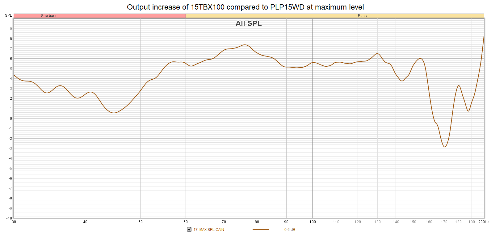
not exactly predictable from T/S parameters. I would always go towards maximum output from a given cab though if transporting them as often adding more subs is not an option.
A cheaper driver like 18TBX100 will reduce maximum per cab output, its very difficult to say how much by from specs alone. We know that the 18SW115 has greater power handling and excursion and so can generalise that it will give greater output but at which frequencies and by how much requires measurment. As an example this is measured maximum output of the same sub (reflex not TH) with two different driver combinations:
not exactly predictable from T/S parameters. I would always go towards maximum output from a given cab though if transporting them as often adding more subs is not an option.
Those are very interesting findings, wish to compare an 18TBX100 to a 18DS115 on a real no simulated measurementrequires measurment. As an example this is measured maximum output of the same sub (reflex not TH) with two different driver combinations:
not exactly predictable from T/S parameters. I would always go towards maximum output from a given cab though if transporting them as often adding more subs is not an option.
Hey @Xoc1 - we've drawn these up ourselves in solidworks over the last few weeks, and had a question about the first part of the horn path after implementing the throat correction.
Image on the left shows the design after throat correct, right is obviously the original design. Is it correct that the throat opens like this in the throat corrected design? It appears that the horn path expands signifiantly in the early parts of the path, and we're concerned (looking at the old design) that this might not be desireable? Any guidance would be greatly appreciated!

Image on the left shows the design after throat correct, right is obviously the original design. Is it correct that the throat opens like this in the throat corrected design? It appears that the horn path expands signifiantly in the early parts of the path, and we're concerned (looking at the old design) that this might not be desireable? Any guidance would be greatly appreciated!
The 113 dimension is perpendicular to the inner baffle when I would expect the measurement to be perpendicular to the horn path centre line. - Which would make it a smaller dimension.
The 147 dimension is right into the corner which will always be oversized!
The 105.9 dim is probably as expected.
Have you created a hornpath sketch using the advanced centreline method as the image of one of my drawings in your screen shot ( Which looks to not be a TH18 drawing), and used that to drive an unfolded sketch?
The unfolded sketch lines are driven by the folded hornpath sketch, (give then an equal to relation), so being parametrically linked will update as you change the speaker layout. That way you can assess any changes you make to the design by rebuilding the speaker model.
The tricky bit is constructing the sketches without adding any auto generated relations that will cause them to become overconstrained.
The overall path is probably not as bad as you think The original design might seem elegant but it assumes a flat pistonic speaker which can be compensated for with VTC and ATC in the simulation. - Or add the cone compensation to the horn path to see how that changes the horn shape.
With this sort of modelling you eventually learn that reducing the width in one area increases the width somwhere else & the overall volume remains the same. Which then leads to a very similar output.
Actual improvements are very hard won and and can take ages to optimise.
The original design had the taper from s1 to s2 - Smaller s1 gives an extended response in the sim but practical experience has shown the effect to be not as pronounced as the theory would suggest.
- Home
- Loudspeakers
- Subwoofers
- TH-18 Flat to 35hz! (Xoc1's design)