Things I noticed in my P3A build.
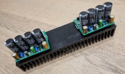
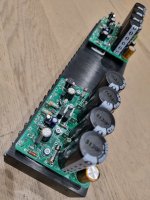
The PCB has 4 x 4700 uf caps. Bypassed with 10nf / 100nf and 10 uf caps.
The input to the board is ac.
I have a power board. With 2x15,000 uF caps. And two 10,000 Uf caps. With all the filters needed.
What I noticed is that when I fee the unit power from the Power board it sounded way better than when I supplied the board with a/c.
At no time does the voltage on the caps dip which means they are fine.
The only thing I need to decide is should I pull the bridge rectifier on the P3A board. And feed it DC from the PSU board.
Or just leave it as is. Also replacing the 10 Amp bridge rectifier with a 35 amp bridge rectifier helped. All tests done with the same EI transformer that gives 35-0-35 dc at 15 amps.
Thank you for the spice file. But when I try to run it I get this error. Plan on trying to figure it out later toning.
Great project. Many PCBs many schematics. Many ideas to try. I have a small collection of P3A type PCBS may make this one too. My philosophy on the psu caps is if the voltage does not dip while playing at the max volume you use the system at if there is no dip or noise on the line you have enough uf.
Im trying to study the impact of picking the right value for the feedback cap and the bootstrap cap values. As well as testing as many transistors types as I can. ie.
Spice Error with both files shared.
=========================
Unknown model type "q2sa1407_syn08" -- ignored
Fatal Error: V1: requires a minimum of 5 parameters. Only 3 specified.
I tried kicads simulation very briefly, but as I have no experience with simulation I can't say much...
External smoothing caps sounding better reminds me of what we discussed about return layout for cap charging pulses that might pollute 0V lines.
So @Bigun, did you try the TGM8 with offboard caps as the main ripple-smoothers, and if so, did it make a difference?
External smoothing caps sounding better reminds me of what we discussed about return layout for cap charging pulses that might pollute 0V lines.
So @Bigun, did you try the TGM8 with offboard caps as the main ripple-smoothers, and if so, did it make a difference?
Last edited:
Member
Joined 2009
Paid Member
I didn’t try with off-board caps, too lazy I suppose! But in principle I would endorse that approach as being better. Put first caps and rectifier close to transformer to keep charging pulses in a small loop and away from the amp.
(I did try the amp initially from a regulated benchtop supply and it sounded fine)
(I did try the amp initially from a regulated benchtop supply and it sounded fine)

OK, I think I will build the TGM8 first as you did (I love small cases), and if I feel the need of extra caps near the transformer I will report the difference it makes. Here is the updated BOM I ordered from Mouser.
Another tip if your scoping all signals and measuring THD. Or just trying to figure out what sounds better.
Make sure that all your low voltage input signals are shielded and the highest quality you can get.
If you cant find anything use cat7 network cables. Though the shielded 3 core used on old tape heads is the best.
I wasted 3 months working on circuits and PCBs and components. Only to find how I faced the table. The presence of my body near the circuit had more impact on harmonics than all my experiments and PSU design ideas.
An inductor between your power filter caps or even a resistor seems to help.
If Im trying various bootstrap and feedback caps. What parameters in spice should I be looking at.
Separate build thread? I'm certainly interested in this, but timid enough to want to see how it goes for you...OK, I think I will build the TGM8 first as you did
Ok, I will report about my build in a separate thread!
Hi there jpk73. I have been studying the schematic that you posted on #1169 with great interest.
I have some TGM8 v5B boards and was pondering perhaps implementing your changes onto my TGM8 build including adding the 'speed up' cap that you show between the bases of Q12 and Q15. Unfortunately, given the position of the power devices under the board, it is not possible to simply extend the legs of the bases of Q12 and Q15 below the board and mount the 1uF cap there with the boards I have. So in the end I may just go with Gareth's 'standard' build with the BOM at #950. But I do have a couple of questions.
You have changed the values of many components to speed up the protection circuit, but I note that you have changed the values of R21, R25 and R26 by only one ohm. Was that fine tuning?
You have removed the 12v zeners D2 and D3 from the gates of the output FETs as suggested by Gareth. But I see that you also removed D4 from the protection FETs. Does the same reasoning re their capacitance apply here?
D4 is back, see my latest files. R21, R25, R26 I didn't change, the value was like that already in the files I used. Probably due to availability, i.e. 150R vs 149R etc. will not matter.
Is it not possible to solder the 1uF with wires to the legs of Q12 and Q15 on the top side of the PCB?
Is it not possible to solder the 1uF with wires to the legs of Q12 and Q15 on the top side of the PCB?
Thanks JPK. Thanks for getting back to me so quickly and clearing that up..... and sorry I did not look at your later files.
Hmmmm....perhaps, a bit fiddly but doable. I think I'll wait until you have completed your build and if all goes well, then I'll give it a go.Is it not possible to solder the 1uF with wires to the legs of Q12 and Q15 on the top side of the PCB?
Ok, it will take me some time. The parts are ordered already. I might have some spare boards left over for you, but I can't promise...
I built the boards, everything seems to work fine, except the green side of the dual LED doesn't go on, only the red at power on for a few seconds and if offset is adjusted for high DC. I double checked the schematic, maybe it's because I tested with a +/-38V PSU. Also I used VOM1271 to drive the mute mosfets. I will carry out more tests and post pictures soon. @Bigun, do you prefer me to open a new thread for my build?
Member
Joined 2009
Paid Member
I’m happy to see you continue in this thread.
That LED comment gives me dejavu, meaning that I may have experienced a similar issue, so it’s worth looking back through the thread for the solution.
edit: post #232, the LED is a mistake from me 🙁
It can be fixed as described but darn it should have put this information somewhere in the first post. I’ll add it.
edit 2: I see that post #314 is where I made my fix. I feel bad about that, I owe somebody a beer.
You fella’s are tempting me to build some more boards myself, to get the TGM8 into my home theatre set-up.
Last edited:
Don't feel bad: I saw the diode in one of the later schematics but ignored it - so actually it's my fault!!
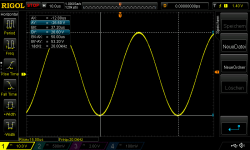
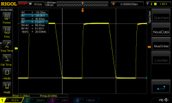
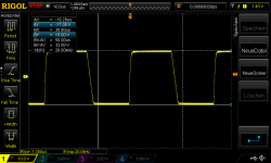
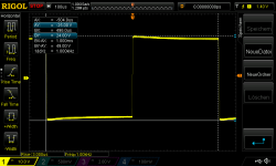
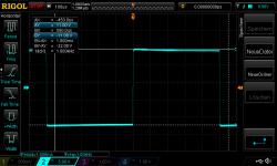
I inserted the diodes as shown in #314, now the LEDs work as intended! Here are some pictures and scope shots taken at the 8R load resistor. Nice and stable up to very high power. Sine is symmetric all the way up, the square waves have some offset (see the blue highlighted "AY" and "BY" values in the box in the upper left corner): more offset with more power and also with higher frequency. Does that indicate a problem or build mistake?
Attachments
Last edited:
Member
Joined 2009
Paid Member
- Home
- Amplifiers
- Solid State
- TGM8 - my best amplifier, incredible bass, clear highs, no fatigue (inspired by Rod Elliot P3a)