A simulation with a DYNA OPT show exactly the problem of instability you have when the output start to go class B. Increasing C2 to 220 or 330p solved it for me.
Last edited:
Doing some further testing this morning using a 6267 instead of the EF806S and saw much better results. (102V on the plate) What was not so good is I also noticed that half of the HT winding was only showing 10Vac and the other half 390Vac.
Checking the mains transformer winding resistance across both halves shows it as open circuit vs my other one which shows 168ohms. It's spec is 410-0-410 @ 180mA which I would have thought is sufficient for this design. I think it'll have to go back to primary windings.
Checking the mains transformer winding resistance across both halves shows it as open circuit vs my other one which shows 168ohms. It's spec is 410-0-410 @ 180mA which I would have thought is sufficient for this design. I think it'll have to go back to primary windings.
The HT winding goes straight from the transformer into the fuses which are quick blow 250mA. I wonder if it was just a premature failure as there doesn't appear to be anything wrong that I can find.
Just an out of interest, how much over the original 5-20's 145mA does the conversion to 6CG7 with CCS add? As far as I can tell, it certainly doesn't add anything close to the 40mA spare that mullard specified for running a preamp/radio receiver.
Think your just unlucky. With your fuses and a valve rectifier unless you shorted out the winding I don't think you will have blown it.
I'm now wearing my "disappointed at myself face" and the dunce hat.
I took the transformer out today in order to pack it to ship back and thought I'll test it again. The "dodgy" side now showed about 1Meg resistance to centre tap which I thought was a little odd as it was totally open circuit yesterday and wiggling the cables showed no difference. Removed the crimp and tested after stripping back some insulation and it all measures good now.
Lets just say I'm having a rethink on using crimps. Diabolical Artificer warned me about the trouble crimps can cause.
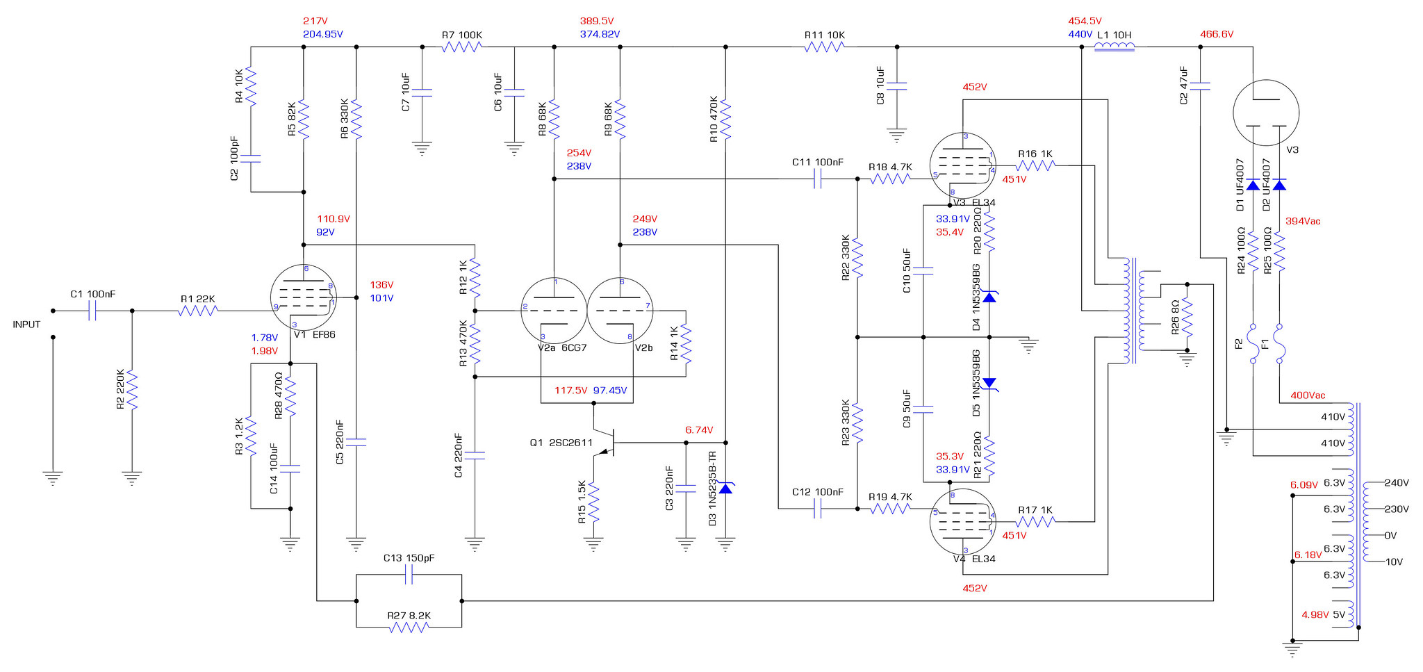
All reconnected now with solder and sleeving. Voltages are now much higher after the rectifier. I think I still need to tweak the resistors around EF86 to get the operating point closer but it's not too far out. I measured all the AC voltages too and added them for what it's worth.
It's performance doesn't look too bad without feedback. Certainly better than the 12AX7 phase splitter. It still gets quite out of shape around 11Vrms output, particularly on the negative cycle. I'm guessing that the V1/V2 operating point is still playing it's part in that. There's also the obvious signs of crossover distortion too.
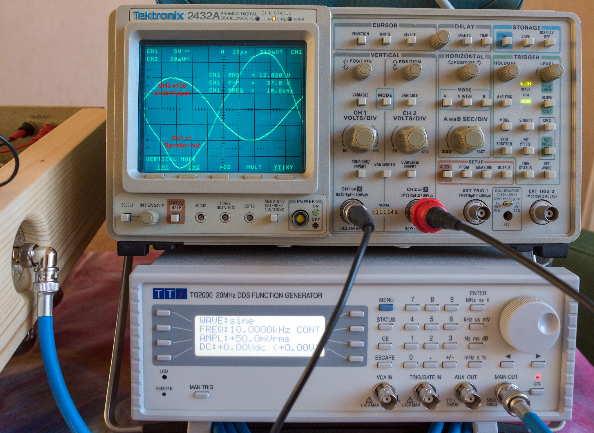
Even a 10K square wave doesn't look bad. The frequency response is remarkably flat at lower power outputs. Towards that 11Vac output, the response starts to fall slowly from 14KHz.

It's performance doesn't look too bad without feedback. Certainly better than the 12AX7 phase splitter. It still gets quite out of shape around 11Vrms output, particularly on the negative cycle. I'm guessing that the V1/V2 operating point is still playing it's part in that. There's also the obvious signs of crossover distortion too.
Even a 10K square wave doesn't look bad. The frequency response is remarkably flat at lower power outputs. Towards that 11Vac output, the response starts to fall slowly from 14KHz.
Yep that's with the 100p for C2. When you make is 220p it will fall off earlier but that's part on the dominate pole. You could measure without C2. The get less crossover distortion you would have to move more to fixed bias making the zeners say 33v and the cathode resistor smaller. But thats with a continuous sinewave rather than music. Maybe R6 = 220k
Last edited:
Those tests above were done with C2/R4 & C13/R27 completely removed. No feedback whatsoever.
Why is the screen voltage on EF86 so high? Won't lowering R6 make it even higher? Reading this suggests a higher screen voltage would increase anode current for a given Vgk. I'm working on the premise that getting the working conditions right for V1/V2 without feedback. Once that is working correctly, I can then deal with the feedback nightmare.
Why is the screen voltage on EF86 so high? Won't lowering R6 make it even higher? Reading this suggests a higher screen voltage would increase anode current for a given Vgk. I'm working on the premise that getting the working conditions right for V1/V2 without feedback. Once that is working correctly, I can then deal with the feedback nightmare.
I made some adjustments to the cathode on EF86 and ran some tests. First thing I tried was removing the 100uF cap and 470R resistor leaving only the 1.2K resistor in place. Zero effect observed, voltages remained the same. I then swapped out the 1.2K resistor for a 1K. I also swapped out the JJ GZ34/KT77's for EL34B/5AR4. The JJ GZ34 clearly has more sag than the sovtek 5AR4 as the voltages out of it were ~10V higher. The behaviour of both V1 & V2 seemed to be far better with the voltages being much closer to expected. I also noticed the asymmetric distortion on the output has now gone, only showing slight signs of crossover distortion as the output passes 13Vrms.
I'm going to look at changing the screen grid resistor on the EF86 and see how that affects things. Looking at trying 470K initially.
This is how things were with just the cathode of EF86 changed.
I'm going to look at changing the screen grid resistor on the EF86 and see how that affects things. Looking at trying 470K initially.
This is how things were with just the cathode of EF86 changed.
Attachments
Higher resistor less screen current. However less gm too so in fact goes the wrong way. The 100uF + 470R improve the LF stability when you close the FB.
Last edited:
Figured as much but from my perspective, I wanted to actually see the effect on the voltages across both V1 & V2. I was surprised at how big a difference it actually made everywhere else, yet the screen voltage change was pretty small.Higher resistor less screen current. However less gm too so in fact goes the wrong way. The 100uF + 470R improve the LF stability when you close the FB.
V1 Anode increased by 26V, G2 decreased by 8V and K decreased by 0.15V. V2 anodes remained the same but K increased by 11V.
Anyway, I put the 330K back in as that seemed to produce voltages in line with expectations considering the higher supply voltages. I can't remember where I read it but it said about the screen being a 1:4 ratio with the anode, so 82K*4=328K
I've connected a speaker to it as is without feedback still. No noise on the output that I can hear and it actually sounds superb without any feedback. Closing the loop and getting the thing stable might be a challenge but if it actually improves on the way it currently sounds, I will be thoroughly impressed. It's been playing for a few hours now at a reasonable level and no signs of red plating.
You will need the LF compensation back in or it will affect the amount of negative feedback across the band. If you make C2 220p and R4 22k and leave the rest the same I think it should be stable. If you are happy without NF then you could reduce the NF amount from 17dB down to 10dB. That will make your life much easier. Don't forget when you connect the 8k2 FB resistor its in parallel with the 1k2 making about 1k and dropping the plate voltage.
Last edited:
I think its better to set screen current rather than screen voltage. Most of the professional circuits seem use a single resistor from HT whereas most diy circuits set the voltage with two resistors. I suspect you get better tolerance to valve variations using the current method. However this is where I don't know. You would have to ask an expert like Mr Summer or Audiowise. However you are showing that the circuit is not that tolerant to EF86 variations.
Last edited:
I've put C4/R28 (470R + 100uF) back in and reconnected the feedback for testing today. I put a 270pF mica cap in for C2 and R4 is still 10K.
HF seems stable with no observed issues other than the expected distortion above 50KHz. LF is not stable yet. Ringing starts to appear around 1KHz 500mV in and increases as the frequency falls.
1KHz @ 500mV in shows a slight wrinkle where the ringing is starting.

@500Hz, It's about as bad as it gets.
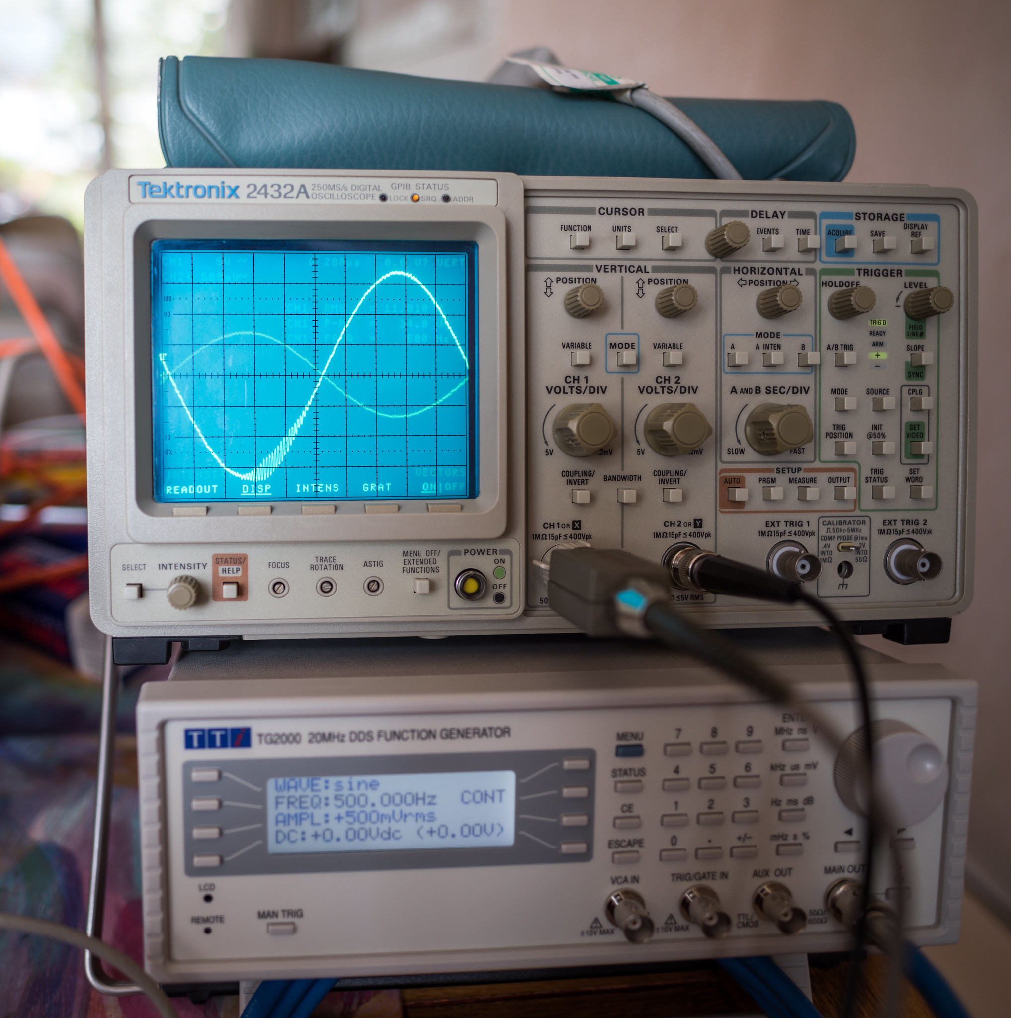
I think the filter network on the input is not cutting in high enough for the sub 20Hz issues. It gets very upset by sub 10Hz inputs which I was expecting to be filtered out at the input.
@10Hz 350mV

I'm going to try changing C11/C12 to 470nF and observe the effects on the LF stability or lack thereof.
HF seems stable with no observed issues other than the expected distortion above 50KHz. LF is not stable yet. Ringing starts to appear around 1KHz 500mV in and increases as the frequency falls.
1KHz @ 500mV in shows a slight wrinkle where the ringing is starting.
@500Hz, It's about as bad as it gets.
I think the filter network on the input is not cutting in high enough for the sub 20Hz issues. It gets very upset by sub 10Hz inputs which I was expecting to be filtered out at the input.
@10Hz 350mV
I'm going to try changing C11/C12 to 470nF and observe the effects on the LF stability or lack thereof.
- Home
- Amplifiers
- Tubes / Valves
- Testing newly built mullard 5-20