Thank you, that is mighty impressive. You've been a great help and remarkably patient helping me with this. It may take me a day or two to finish the building work as it currently lacks any side panels for mounting most of the bits. I will keep you posted.View attachment 849024
With new model of transformer FB is not as critical, with C13 LF is stable with EL34 coupling at 100nF. Enjoy.
Would you mind sharing the symbol (.asy) file? How about the asc file as well? Just zip it all up.View attachment 849024
With new model of transformer FB is not as critical, with C13 LF is stable with EL34 coupling at 100nF. Enjoy.
Thanks
Wayne (from Wayne) 😀
Got the constant current sink built on veroboard and fitted it to the main turret board. Will the transistor need a heatsink?

Finished off all but the feedback section of the turret board today.
Finished off all but the feedback section of the turret board today.
Finally finished building this modified version a few days ago. After a lot of checks to make sure the wiring was right, I finally tested it this afternoon without the feedback connected. No obvious disasters but something is clearly not right with the phase splitter. I'm seeing little signal out and a lot of distortion. I'll get some photos of the waveforms once I have a table to work at.
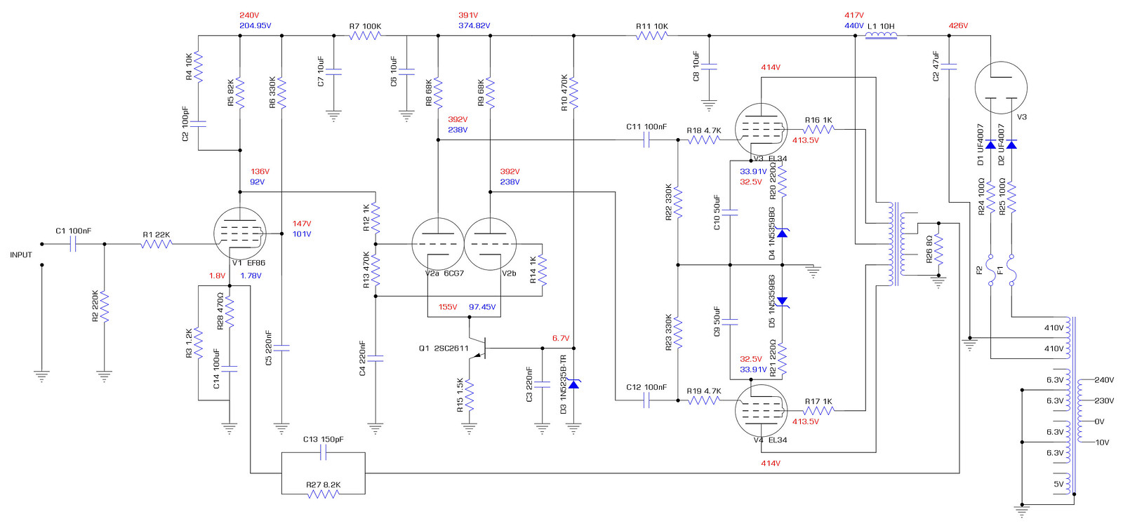
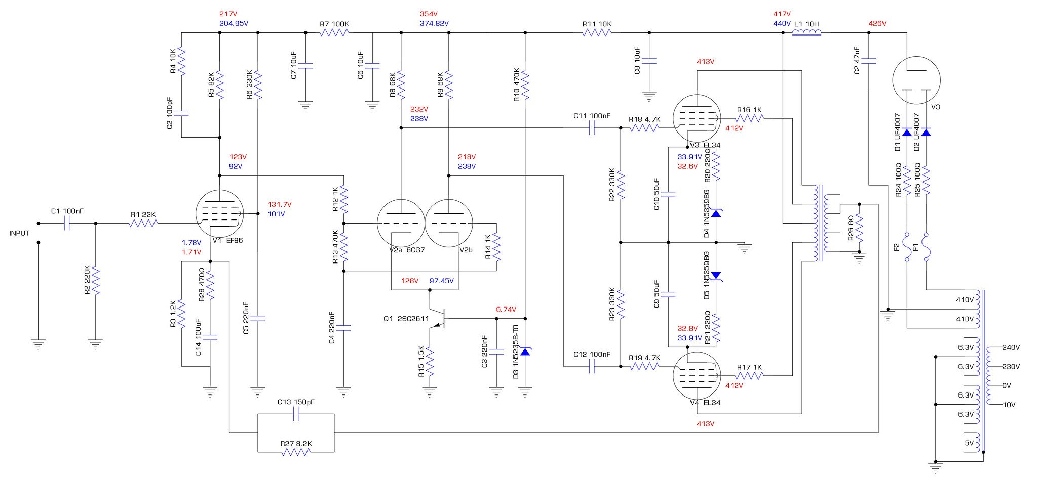
This is the schematic exactly as built. Blue voltages are the simulated values from LT spice. Red are what I have measured. The anode of EF86 looks great but the output of 6CG7 looks awful and notably, the anode voltage on 6CG7 is way over where it should be.
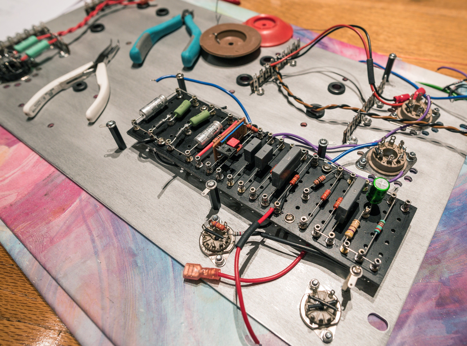
This is how it is laid out. The brown wire that isn't connected and the 10K resistor that isn't connected are both feedback related and not connected yet.


This is the schematic exactly as built. Blue voltages are the simulated values from LT spice. Red are what I have measured. The anode of EF86 looks great but the output of 6CG7 looks awful and notably, the anode voltage on 6CG7 is way over where it should be.
This is how it is laid out. The brown wire that isn't connected and the 10K resistor that isn't connected are both feedback related and not connected yet.
I think you may have an error in your CCS I don't think its sourcing any current check the voltage across the 1k5 resistor maybe the transistor is wired up wrong. That 1k5 is 1k5 not 15k.
Last edited:
Having just re-checked my drawing of the CCS board and the datasheet for 2SC2611, it appears that I have successfully mirrored the transistor connections. I've connected the base and emitter backwards which would explain quite a lot. It was wrong in my drawing which is why when I checked it, I missed the error.
Took the transistor out and checked it. It tested ok so I put it back in the correct way around and reran the test with no feedback. Voltages seem to be a fair bit better, possibly a bit low if anything, which I can correct by moving the primary over to 240V instead of 250V.
Some slight oddities I noticed:
- The measured voltage at the anodes of 6CG7 differ by 3V
- ~100mV of noise on the anodes of 6CG7 at idle
- EF86 clips on the positive half of the waveform @ ~70mV which throws the balance
This is an example of what I mean by the limited output power. It's clean at 60mV input across the whole frequency range.

It starts to distort around 80mV and by 100mV input it's well gone.
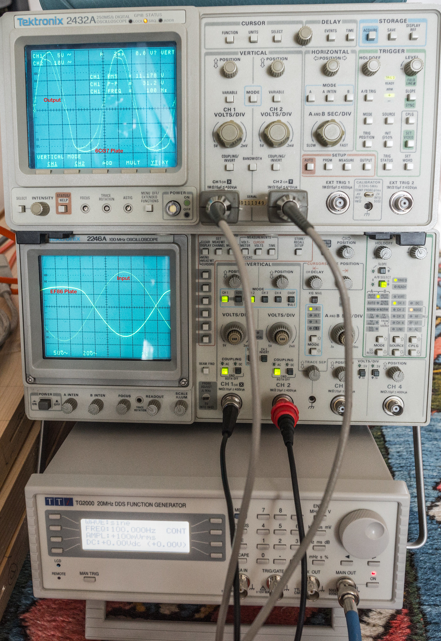
I've labelled the traces above as to what each is. EF86 plate has a x100 probe and the input is an x1 probe, everything else is an x10 probe.
I wonder if 6A3Summer may be on to something with C14/R28 on the cathode of EF86.
Some slight oddities I noticed:
- The measured voltage at the anodes of 6CG7 differ by 3V
- ~100mV of noise on the anodes of 6CG7 at idle
- EF86 clips on the positive half of the waveform @ ~70mV which throws the balance
This is an example of what I mean by the limited output power. It's clean at 60mV input across the whole frequency range.
It starts to distort around 80mV and by 100mV input it's well gone.
I've labelled the traces above as to what each is. EF86 plate has a x100 probe and the input is an x1 probe, everything else is an x10 probe.
I wonder if 6A3Summer may be on to something with C14/R28 on the cathode of EF86.
Last edited:
Super yor are getting there. The plate voltage will not be quite the same on the 2 6CG7 as they are not matched internally. However you should see the AC peak to peak voltage should be very similar. You only need enough voltage to drive the output stage. Don't forget with no NF the gain will be much much higher. If the second stage saturates you will see current though R12 which will clip the first stage too. Lift R12 to check this.
Last edited:
Try R6 = 220k to increase the screen voltage. Unfortunately LT spice model may not be accurate for the EF86. Mr Summer may be better here at giving you a little practical advise. Can you make it clear on your scope which is CH1 and CH2 and the voltage ranges you are set for each channel. I would try another EF86 too.
Cheer.
Cheer.
Last edited:
I can get what you see if there's not enough current in the first stage. You want the EF86 plate voltage to be about 85-100v. Try dropping screen resistor to 220k. Try dropping cathode resistor to 1k from 1k2. EF86 may be low on emission.
Don't forget the 8k2 FB resistor when connected through the OPT to ground will also draw a bit of current dropping the plate voltage. You need <95v there.
Sorry, I forgot to write on the channels for the scope shots.
2432 CH1 - Output x10
2432 CH2 - 6CG7 plate x10
2246 CH1 - Input x1
2246 CH2 - EF86 plate x100
I'd missed your posts above prior to connecting the feedback and re testing. Once the output voltage exceeds ~ 8Vrms, it starts to oscillate. It seems consistent across the a wide range of frequencies.
1KHz @ 350mV in it's ok. Centring of the trace on the 2246 seems off as it keeps moving. There may be issues with the scope.

1KHz @ 390mV in

400Hz @ 390mV

100Hz @ 390mV

I'll look at reducing the screen resistor to 220k. I have two other EF86, which are vintage GE 6267's. Currently the valves being used for the test are:
Tung-Sol EF806SG
EH 6CG7
JJ KT77
2432 CH1 - Output x10
2432 CH2 - 6CG7 plate x10
2246 CH1 - Input x1
2246 CH2 - EF86 plate x100
I'd missed your posts above prior to connecting the feedback and re testing. Once the output voltage exceeds ~ 8Vrms, it starts to oscillate. It seems consistent across the a wide range of frequencies.
1KHz @ 350mV in it's ok. Centring of the trace on the 2246 seems off as it keeps moving. There may be issues with the scope.
1KHz @ 390mV in
400Hz @ 390mV
100Hz @ 390mV
I'll look at reducing the screen resistor to 220k. I have two other EF86, which are vintage GE 6267's. Currently the valves being used for the test are:
Tung-Sol EF806SG
EH 6CG7
JJ KT77
Yep 123v is too high. Get to the bottom of this first as it may affect gain and the NFB. How much does the gain drop when the fb is connected (at 1KHz?).
At least the FB is not a case of hopeless! To get the FB right set the unit up so its just oscillating. Then try altering C2 and R4 and C13. Try each separately. Say R4 = 22K R4 = 4k7. C2 = 47p C2 = 220p, C13 47p 100p 220p. Recode what makes it worse and better on a piece of paper.
I would try C2 = 220p first.
I would try C2 = 220p first.
Last edited:
Without feedback, 60mVrms in gave 9.6Vrms out. Gain calculator says 44.0824dB
With feedback 350mVrms in gave 7.55Vrms out. Gain calculator says 26.677578dB
17.4 ish dB drop with feedback @ 1KHz if the above is calculated correctly.
I get similar numbers out for other tested frequencies.
With feedback 350mVrms in gave 7.55Vrms out. Gain calculator says 26.677578dB
17.4 ish dB drop with feedback @ 1KHz if the above is calculated correctly.
I get similar numbers out for other tested frequencies.
- Home
- Amplifiers
- Tubes / Valves
- Testing newly built mullard 5-20