Yep try bigger C11/C12 and try smaller. You can also try bigger C4 say 470uF. If the transformer model is wrong which it is I cannot advise. You could also do away with C4 too but it will change the FB gain and the input gain. Tip is to keep notes of what improves and what makes it worse.
Last edited:
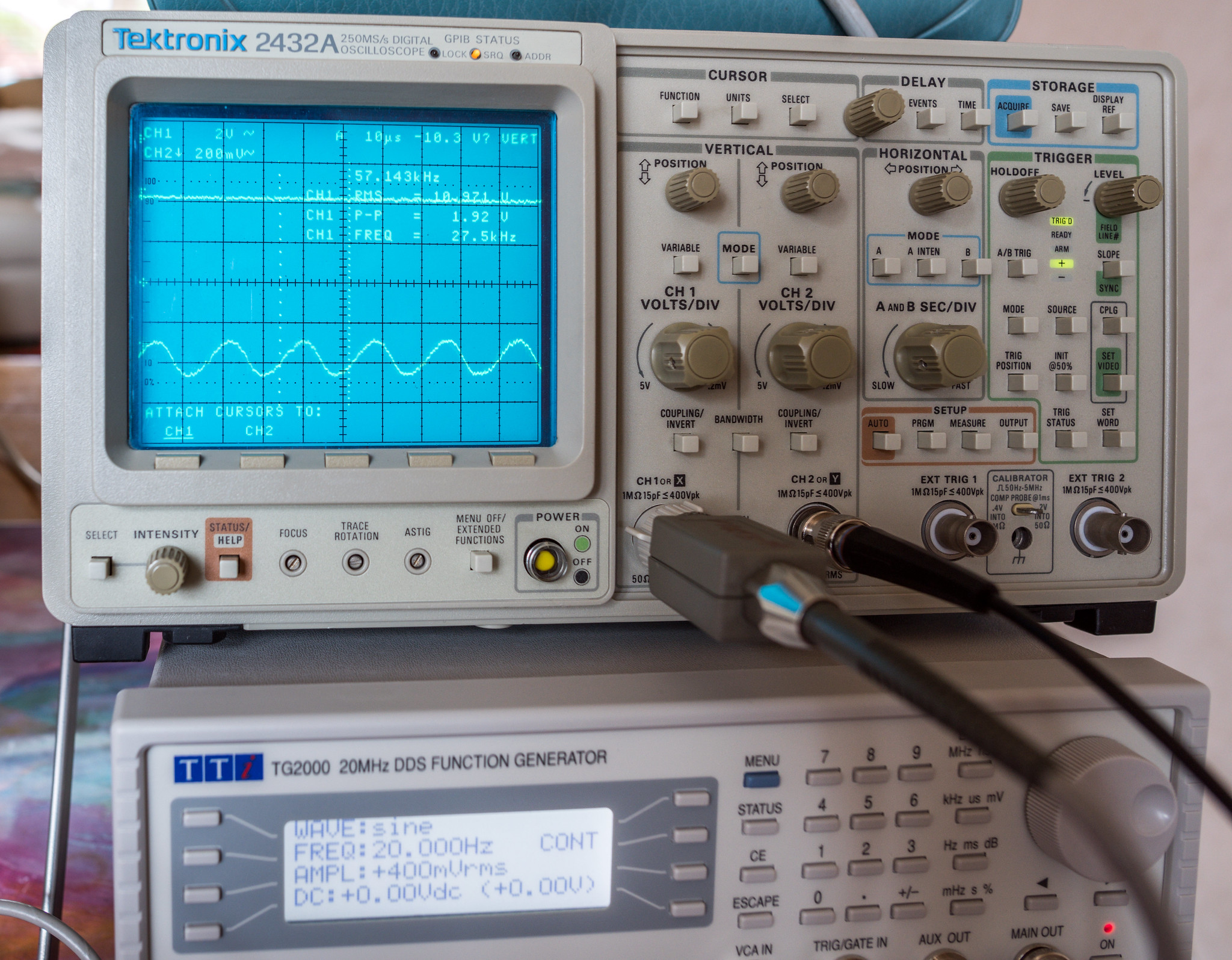
The frequency of the oscillation I'm seeing with a 20Hz input is around 57-58KHz. This oscillogram is just zoomed in on the ringing/oscillation.
C11/C12 being 470nF didn't appear to make much if any difference on their own. I've now increased R4 to 22K and that had a pronounced effect on it. The start point where I see the ringing/oscillation is now down from 1KHz to 400Hz and the severity is now less.

Comparison at 100Hz 500mV input. Left is C11/C12 @ 100nF & R4 @ 10K, right is C11/C12 @ 470nF & R4 @ 22K. C2 was 270pF for both.

I've attached a schematic showing the changes in value up to now. It's improving as I can no longer get any misbehaviour above 500Hz.
C11/C12 being 470nF didn't appear to make much if any difference on their own. I've now increased R4 to 22K and that had a pronounced effect on it. The start point where I see the ringing/oscillation is now down from 1KHz to 400Hz and the severity is now less.
Comparison at 100Hz 500mV input. Left is C11/C12 @ 100nF & R4 @ 10K, right is C11/C12 @ 470nF & R4 @ 22K. C2 was 270pF for both.
I've attached a schematic showing the changes in value up to now. It's improving as I can no longer get any misbehaviour above 500Hz.
Attachments

It probably will not help, but try this anyway:
Put a 100 Ohm resistor (base stopper") from the base to the parallel 220nF / Zener.
As the circuit is now:
The base is at RF ground.
The Emitter is 1.5k in parallel with stray capacitance to ground.
The Collector is at who knows what impedance at frequencies near the fT of the transistor.
Many an oscillator has been made at fractions of fT, at fT, and even beyond fT.
At fT, a little wire inductance, and a little stray capacitance goes a very long way to building an oscillator.
I am reminded when an engineer wanted to increase the current output capability of an op amp by using emitter followers.
The NPN collector was tied to + supply (it was bypassed to ground at RF).
The PNP collector was tied to - supply (it was bypassed to ground at RF).
The NPN and PNP emitters were tied together.
The NPN and PNP bases were tied together.
Everything worked great, until the signal voltage was varied (and of course output current was varied into the load).
The voltage change and current change was making the effective fT of the transistors change; and also changed the junction capacitances.
When the fT, junction capacitances, and the lead inductances and circuit wiring inductances all "came together" you had an oscillator.
Just so you can be certain that the op amp was not the problem, the op amp frequency capability was orders of magnitude lower than the 350 MHz fT of the NPN and PNP.
Another key fact is that the oscillation was not constant, it only occurred at certain voltage portions of the signal swing, similar to one of your oscilloscope photos.
Last edited:

So it just simple NFB being too marginal. As its at 58KHz is just where the NFB goes through unity gain. How much does the gain drop when you connect the NFB? It should be 17dB. My simulation is showing 22dB which is too much. So if your happy with sound open loop then start with less FB say R27 = 12k. Mr Summer does point out that the NPN could oscillate if the collector load looks inductive and one should put 100R in series with the base. However this will go off at several tens MHz, but could affect the voltages on V2 plates if it does. However in this case I don't think it is. Nevertheless it is good design practise.
Last edited:

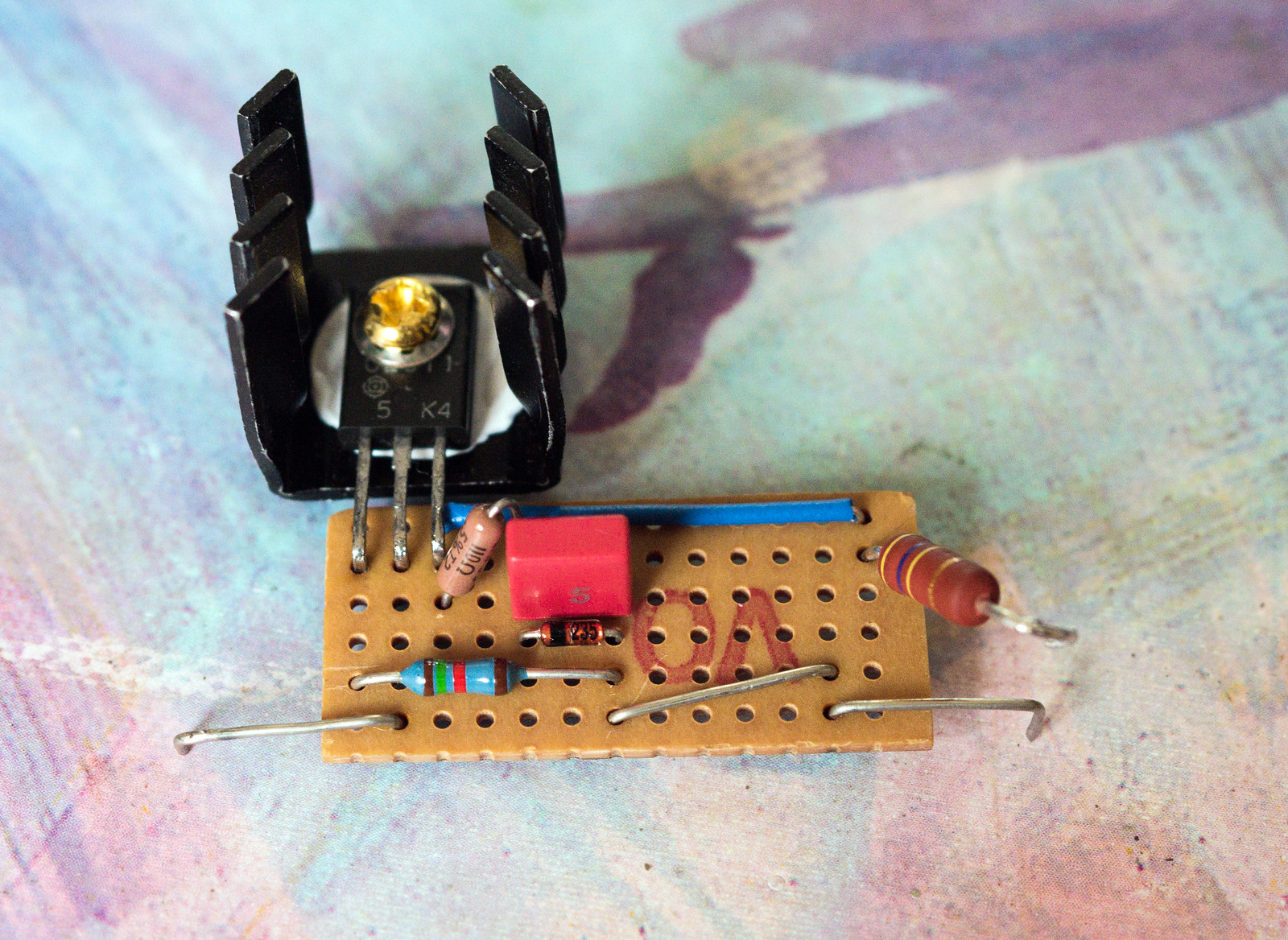
A very good suggestion, certainly one that would not have crossed my mind. Looking at the CCS as I built it, I should be able to put a series 100R in place of the green link wire which links the base to the cap and zener. (the zener is obscured by the cap)It probably will not help, but try this anyway:
Put a 100 Ohm resistor (base stopper") from the base to the parallel 220nF / Zener.
As the circuit is now:
The base is at RF ground.
The Emitter is 1.5k in parallel with stray capacitance to ground.
The Collector is at who knows what impedance at frequencies near the fT of the transistor.
Many an oscillator has been made at fractions of fT, at fT, and even beyond fT.
At fT, a little wire inductance, and a little stray capacitance goes a very long way to building an oscillator.
I am reminded when an engineer wanted to increase the current output capability of an op amp by using emitter followers.
The NPN collector was tied to + supply (it was bypassed to ground at RF).
The PNP collector was tied to - supply (it was bypassed to ground at RF).
The NPN and PNP emitters were tied together.
The NPN and PNP bases were tied together.
Everything worked great, until the signal voltage was varied (and of course output current was varied into the load).
The voltage change and current change was making the effective fT of the transistors change; and also changed the junction capacitances.
When the fT, junction capacitances, and the lead inductances and circuit wiring inductances all "came together" you had an oscillator.
Just so you can be certain that the op amp was not the problem, the op amp frequency capability was orders of magnitude lower than the 350 MHz fT of the NPN and PNP.
Another key fact is that the oscillation was not constant, it only occurred at certain voltage portions of the signal swing, similar to one of your oscilloscope photos.

I'll try the increase in R27 a go. Should I drop the value of R4 back to 10K or leave it at 22k? (component numbering as per my schematic)So it just simple NFB being too marginal. As its at 58KHz is just where the NFB goes through unity gain. How much does the gain drop when you connect the NFB? It should be 17dB. My simulation is showing 22dB which is too much. So if your happy with sound open loop then start with less FB say R27 = 12k. Mr Summer does point out that the NPN could oscillate if the collector load looks inductive and one should put 100R in series with the base. However this will go off at several tens MHz, but could affect the voltages on V2 plates if it does. However in this case I don't think it is. Nevertheless it is good design practise.
Out of interest, how does your simulation behave if the power source is bumped up from 440V to 465V as I'm seeing?
Be careful, the negative feedback resistor (12k to 8.2k) was not the only change.
Post # 303:
Schematic: Pentode Plate Dominant Pole Network : 22k & 270 pF
* 26,800 Hz
Post # 306: Schematic: Pentode Plate Dominant Pole Network : 22k & 220 pF
* 32,900 Hz
Post # 307:
Schematic: Pentode Plate Dominant Pole Network : 10k & 270 pF
* 58,900 Hz
Those are all different bandwidth.
And they are all different gain at bandwidth (according to 22k versus 10k).
One change makes a difference.
One apple.
Two changes makes a bigger difference.
One apple and one orange.
Kei,
I love your Tektronix oscilloscopes.
I have one Analog Tek scope; And one Digital Tek scope, with FFT.
Last edited:
Just saying if the basic NFB is too high then its a bad starting point. I thought we had designed for 17dB NFB but I think the sowter transformer model I did is wrong. When I put the DYNA one in (4300/4) impedance ratio I get 22dB which is far too much for a valve amp like this. Dominant pole is with 82k the 22k forms the zero. So
220pF + 82k = 8.8KHz
Then zero at 220pF + 10k = 50KHz.
I would put R4 back to 10k. I found 4k7 was better, but I don't have your transformer.
First thing to check is how much gain drops at 1KHz when you connect NFB, should be 17dB. If you give us this figure could you also quote the R27 value you are using.
Last edited:
Different models of output transformers have different frequency response, and different phase response.
They also have different "ring" frequencies.
We all know this.
But they also have different insertion losses. An insertion loss of 1.5dB versus 0.5 dB changes the open loop gain of the amplifier (not by much, but a dB is a dB).
The other day, I was repairing a non-feedback 2A3 push pull amplifier for a friend.
I had the opportunity to measure the transformer's frequency response.
And I measured the "ring" frequency.
Then I measured the primary DCR and secondary DCR (the dominant causes of insertion loss).
The frequency response, "ring" frequency, and insertion losses were Very Good!
Guess the manufacturer of the output transformer:
.
. .
. . .
. . . .
. . . . .
. . . . . . . . . Monolith
(I can not afford those, but I might break down and purchase a pair someday)
Last edited:
I've come unstuck a few too many times making too many changes and not knowing which change had what effect. Ironically, I wanted an oscilloscope for years but couldn't afford one. Then I got given two in one year as the TV studio I worked at were getting rid of a lot of their old gear. Th 2432 has option 5 Video Waveform Measurement System.Be careful, the negative feedback resistor (12k to 8.2k) was not the only change.
Post # 303:
Schematic: Pentode Plate Dominant Pole Network : 22k & 270 pF
* 26,800 Hz
Post # 306: Schematic: Pentode Plate Dominant Pole Network : 22k & 220 pF
* 32,900 Hz
Post # 307:
Schematic: Pentode Plate Dominant Pole Network : 10k & 270 pF
* 58,900 Hz
Those are all different bandwidth.
And they are all different gain at bandwidth (according to 22k versus 10k).
One change makes a difference.
One apple.
Two changes makes a bigger difference.
One apple and one orange.
Kei,
I love your Tektronix oscilloscopes.
I have one Analog Tek scope; And one Digital Tek scope, with FFT.
The original measurement suggested approximately 44dB open loop gain previously, however that was with a different set of valves. Currently in closed loop with the EL34's in, I'm seeing about 27dB gain.Just saying if the basic NFB is too high then its a bad starting point. I thought we had designed for 17dB NFB but I think the sowter transformer model I did is wrong. When I put the DYNA one in (4300/4) impedance ratio I get 22dB which is far too much for a valve amp like this. Dominant pole is with 82k the 22k forms the zero. So
220pF + 82k = 8.8KHz
Then zero at 220pF + 10k = 50KHz.
I would put R4 back to 10k. I found 4k7 was better, but I don't have your transformer.
First thing to check is how much gain drops at 1KHz when you connect NFB, should be 17dB. If you give us this figure could you also quote the R27 value you are using.
About 2 months ago I did some basic measurements on the transformer with some jury-rigged affair to get a frequency response and phase shift plot. This is what I got for my Sowter UP21. This is the spec page on the sowter site for the transformer. Monolith are a tad more expensive than the Sowters that I bought.Different models of output transformers have different frequency response, and different phase response.
They also have different "ring" frequencies.
We all know this.
But they also have different insertion losses. An insertion loss of 1.5dB versus 0.5 dB changes the open loop gain of the amplifier (not by much, but a dB is a dB).
The other day, I was repairing a non-feedback 2A3 push pull amplifier for a friend.
I had the opportunity to measure the transformer's frequency response.
And I measured the "ring" frequency.
Then I measured the primary DCR and secondary DCR (the dominant causes of insertion loss).
The frequency response, "ring" frequency, and insertion losses were Very Good!
Guess the manufacturer of the output transformer:
.
. .
. . .
. . . .
. . . . .
. . . . . . . . . Monolith
(I can not afford those, but I might break down and purchase a pair someday)
If I am reading it correctly your first transformer pole (45 deg) is at 25KHz which is really quite low. Typically it should be more like 50KHz. It does match up with their spec of bandwidth 50KHz. Did you drive the transformer from the input or through a source resistor? Anyway I suggest you drop the NFB a bit (say R27=12k) to see if you can get the system more stable. Without a transformer in front of me I don't think I can do a model for you.
Last edited:
I've had a good look through my component stash and could not find any 12K resistors. The closest I have is either 10K or 15K. I also put a 110R resistor on the base of the transistor. (Couldn't find any sensibly sized 100R resistors)
I've tried R27 as 10K without making any other changes and it appears that other than a difference in gain, the amount of oscillation remains pretty much identical. This is with R4 @ 22K, C2 at 270pF and C13 still at 150pF.

I've tried R27 as 10K without making any other changes and it appears that other than a difference in gain, the amount of oscillation remains pretty much identical. This is with R4 @ 22K, C2 at 270pF and C13 still at 150pF.
The drop in gain going from 8.2K to 10K looks to be approximately 1.4-1.5dB
(420mV to get the same output as I got with 500mV before)
(420mV to get the same output as I got with 500mV before)
Sorry baudouin, I've retested it for you now. With the same valves in place this is what I have got for gain across open loop and then each feedback resistor.
Open loop = 49.54dB
Closed loop 8.2K = 27.31dB (22.23dB feedback)
Closed loop 10K = 28.75dB (20.79dB feedback)
I guess the gain has risen partly due to the higher HT voltage I'm seeing with the 5AR4. Not sure on the difference between the EL34's and the KT77's as the transconductance written on the matching labels is a fair bit higher for the EL34's. (10.8 vs 8.5, there is also a box labelled as "PC" showing 59 for the EL34's and 49.5 for the KT77's)
In any case, that helps explain the issue if that is supposed to be 17dB.
Last edited:
OK your looking for about 17dB NFB, so like my simulation that's too high to get the thing stable. So I'am thinking 15k or 18k.
Last edited:

- Home
- Amplifiers
- Tubes / Valves
- Testing newly built mullard 5-20