Interestingly I can get better results by taking the NFB from the 4R tap and using 10k+270p for the feedback components. All this seems to indicate its not the best transformer at HF.
I dug out an 18K resistor and did another test run. It now appears to be stable. With R27 @ 18K I'm seeing 33.26dB gain so about 16.3dB of feedback.I have gone back to your original transformer data and corrected my model of the OPT. These are the new vales I get.
View attachment 863832
This is how things look now.
100Hz @ circa 11.5Vrms out (matches the previous testing)

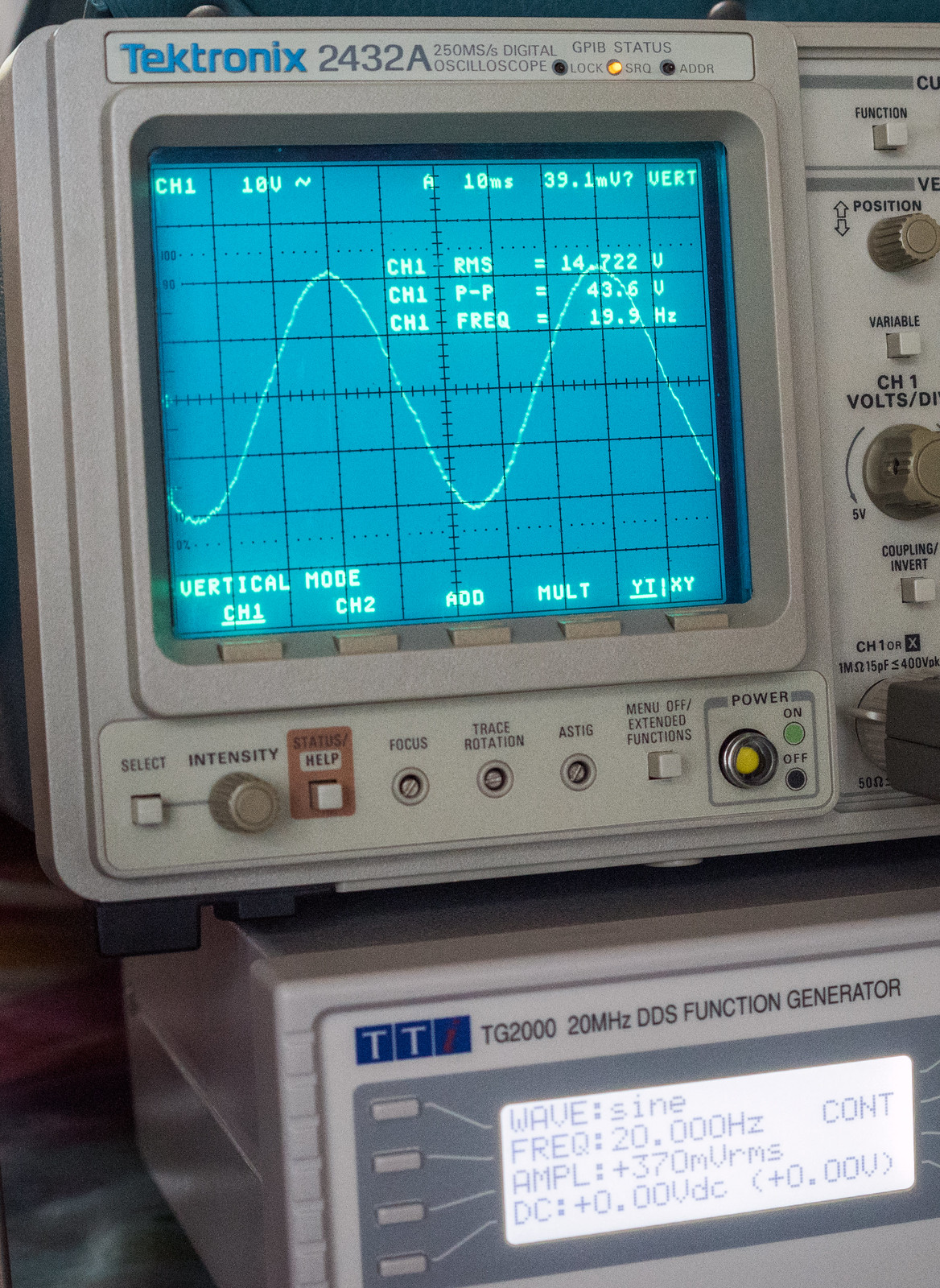
100Hz @ the limit before it distorts heavily

20Hz @ the limit
1KHz square

10KHz square. The rounding over at the rise and fall appear to be in the input signal if taken after the input veroboard suggesting stray capacitance?

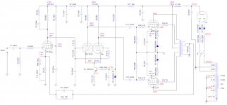
Schematic as things stand. Also note the voltage at C2 and L1 are quite a bit higher than your spice model.
An externally hosted image should be here but it was not working when we last tested it.
That ties in with what Sowter quote about the tapped secondaries having inferior HF bandwidth. I wish I'd read that before I bought them as I'd have gone for either multiple secondaries or a single 8 ohms secondary.Interestingly I can get better results by taking the NFB from the 4R tap and using 10k+270p for the feedback components. All this seems to indicate its not the best transformer at HF.
Overall, I'm quite pleased as I've had hell getting this thing stable. It would be nice to be able to get a flatter frequency response but I'm beginning to think that is borderline impossible with the current components. (mainly the output transformers)
Last edited:
If that's 10KHz square that's very very good. The simulation shows you would actually get the same output power on the 4R configuration even though you are driving 8R. If you do this drop R27 to 10K. You may get better coupling. The error was having too much NF in the first place. Well done and try some speakers. It not really possible to know what you are getting with OPT things like leakage inductance are often measured at LF and there's no figure for primary capacitance. Hammond do a 1650H which digikey/mouser have. Your traces are much much better than your original scope traces with the 12ax7 driver.
Last edited:
This is what I mean by the rounding over showing on the input signal. It doesn't show at the input socket but does show at the point the input signal leaves the small veroboard.If that's 10KHz square that's very very good. The simulation shows you would actually get the same output power on the 4R configuration even though you are driving 8R. If you do this drop R27 to 10K. You may get better coupling. The error was having too much NF in the first place. Well done and try some speakers. It not really possible to know what you are getting with OPT things like leakage inductance are often measured at LF and there's no figure for primary capacitance. Hammond do a 1650H which digikey/mouser have. Your traces are much much better than your original scope traces with the 12ax7 driver.

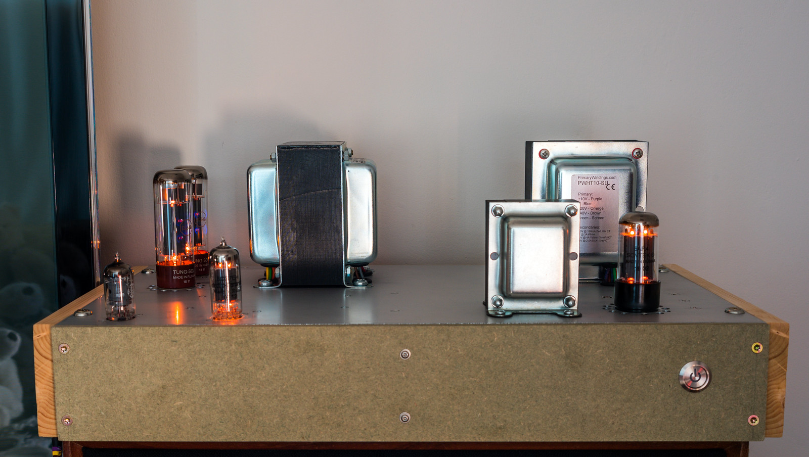
Anyway, I have zero complaints with the sound. The performance seems to be excellent. I'm not sure it's worth fiddling further if the benefit is negligible. That said, ideally, I'd like to build it into a more compact chassis as it is quite a monster compared to the earlier wooden constructions. I've given it a thorough testing today and it's been great. 3 hours on one set of valves and about 4 hours on the other matching set.
The rounding is just bandwidth limiting of the amp. I think you will find its flat up to 20KHz sine wave. Anyway I am chuffed to bits its what you wanted and its been a good learning exercise for all.
I've run the amp with every set of valves I have and have no issues except with the Tung-Sol EF806SG which clearly has issues. I get a lot of hiss and clearly the operating point is wrong so I think I may have a dodgy valve. Both NOS GE 6267's work great.
Hiss, wrong operating point = faulty valve unless for some reason its oscillating at VHF. Yep I just read the bit about Sowter and secondary winding - its quite buried. I think it should be made more clear on the buying page as it does not indicate the HF changes here. You would be able to get more NFB at HF with the quad secondary I am sure, but I don't think you will hear any difference other than the amp may be a bit brighter due to lower damping factor at HF. Its no bad thing with my ears.
Last edited:
Perhaps the "trick" used in "El Cheapo" is applicable here. "Peak" the phase splitter's frequency response by using inductive wirewound resistors as the plate loads. Open loop gain increases, as the frequency rises.
I'm highly tempted to buy a few more of these NOS GE 6267's from langrex before they're all gone as they appear to be excellent and they are fairly cheap.
C11/C12 on my drawing are 470nF vs 100nF on yours and R3 is still 1K vs 1.2K. I've attached the schematic to the board this time as altering the privacy settings to public/private on flickr changes the URL of the image.
Reading back what was written in the elektor article about C11/C12 makes me wonder if perhaps I am best off putting them back to 100nF.
Just looking back at this drawing, I've got quite a few differences compared with how it is currently.I have gone back to your original transformer data and corrected my model of the OPT. These are the new vales I get.
View attachment 863832
C11/C12 on my drawing are 470nF vs 100nF on yours and R3 is still 1K vs 1.2K. I've attached the schematic to the board this time as altering the privacy settings to public/private on flickr changes the URL of the image.
Reading back what was written in the elektor article about C11/C12 makes me wonder if perhaps I am best off putting them back to 100nF.
In the original design, the screen coupling capacitors for the output
valves (C9 & C10) had a value of 470nF. The current through the output
valves proved to have rather large fluctuations at a very low frequency
(0.2–0.5 Hz), which were also present at the loudspeaker output. This was probably due to small variations in the negative grid voltage. Since these fluctuations have a small amplitude and the output transformer has a large self-inductance, they are not blocked by the output transformer, and they find their way to the amplifier input via the negative-feedback network. This phenomenon was reduced to an accept-able level by decreasing the value of
C9 and C10 to 100 nF. This does not have any audible effect on the reproduction of low frequencies.
Certainly sounds like a novel idea. How would that affect the feedback loop stability though?Perhaps the "trick" used in "El Cheapo" is applicable here. "Peak" the phase splitter's frequency response by using inductive wirewound resistors as the plate loads. Open loop gain increases, as the frequency rises.
Attachments
Last edited:
Zener diodes and self bias resistors in the output tube cathodes, gives you combination bias.
Are the self bias resistors able to match the output tube currents?
Why not just change the self bias resistor to a higher resistance, and take out the zener diodes?
The higher the self bias resistance, the better the tubes will tend to match their two quiescent currents.
If there are different quiescent currents in the two output tubes, your output transformer will suffer from early saturation.
Last edited:
The zeners are there to get somewhere between self and fixed bias. The actual voltages are shown in red.
The problem with pure self bias is that with large signals (when you get to cut off on one side) to current tries to increase causing the average voltage to go up on the cathodes over a few cycles and bias out of conduction which results in crossover distortion which is very unpleasant. The original solution was to put more quiescent current which starts to red plate the valves. I like the term combination bias. The zener/resistor combination restrict this increase in voltage to a smaller value. Even with 24v zeners you can see on the scope some crossover distortion at full power. However making the zener voltage higher will give less tolerance to the spread of different valve pairs and may need lower grid bias resistors. Its a compromise.
The valves are matched pair so you can see from the voltages they are balanced.
Last edited:
AS for the LF the circuit around C4 helps a lot. The way to check is to sweep (at 1W say) from 20Hz down to 1Hz. The output rolls off all is fine. If it has a significant peak at 2Hz then try dropping the driver coupling caps from 470n to 100n.
Was testing today to finish my frequency / dB plot and noticed that sub 12Hz I still get some oscillation, however, it is accompanied by a ticking noise from the output transformer which makes me think it's motorboating. More pole problems no doubt..

A closer look at it.

Anyway, this is the graph I ended up with. As I had also plotted results for the earlier Claus Byrith version, that can also be seen on there, both open and closed loop. For those that want to see the numbers and formulae, here is the link to the sheet.

A closer look at it.
Anyway, this is the graph I ended up with. As I had also plotted results for the earlier Claus Byrith version, that can also be seen on there, both open and closed loop. For those that want to see the numbers and formulae, here is the link to the sheet.
I think that still maybe HF oscillation rather than motor-boating the driver will have to work hard at 10Hz and is probably clipping. It may go back to the OPT you have. I would not worry. The only one that looks problematic at LF is the elector CL.
The reason for suspecting motorboating was the faint tick, tick, tick noise coming from the amp. (guessing it's the OPT) The graph suggests it should be stable as there is no sign of a rise in gain. I'm not overly worried at this point as I have tried to upset the applecart under normal usage connected to a speaker and I can't get it to misbehave.I think that still maybe HF oscillation rather than motor-boating the driver will have to work hard at 10Hz and is probably clipping. It may go back to the OPT you have. I would not worry. The only one that looks problematic at LF is the elector CL.
Out of curiosity, why does the elektor design have such a steep HF roll off? It gets out to ~50KHz at a similar level to the current design then drops off very quickly.
Don't know sorry. Instability can set in when something get near clipping as this causes the FB gain to drop suddenly. So just cause its stable for small signals does not mean the same thing for large as many of your scope traces have shown.
Last edited:

CaterpillarSK
OK what you are suggesting looks good. The driver works well at a higher voltage and gives enough string for the KT88. I've increased the current here to 6ma. You are getting +/- 42v on the 8R load but you are probably exceeding the screen and plate dissipation - however that's on the peaks. I am finding the OPT needs to be nearer to 3K rather than 4K for optimum power. Note you need quite a negative rail.
Last edited:
How exactly were you testing? Were you sweeping the frequency, or manually reducing or increasing slowly to see the response?Was testing today to finish my frequency / dB plot and noticed that sub 12Hz I still get some oscillation, however, it is accompanied by a ticking noise from the output transformer which makes me think it's motorboating. More pole problems no doubt.
An LF resonance due to the OPT primary inductance could have a substantial pull-in effect as the resonance frequency is approached, and the primary signal voltage increases, causing the primary inductance to likely increase, causing the resonance frequency to lower, causing ...... Especially if the feedback loop is in play. And the resonance frequency will likely change with test signal level, as that directly relates to output stage primary voltage signal, and hence primary winding inductance.
The other interactions are the electrolytic caps around that first stage. The 8uF B+ decoupling will be having less and less effect and the phase shift from that 8uF may not be helping your stability as much as was designed for (the 100k plate load changes to look like 100k+270k). Also the impedance of the cathode 2k2 starts to change.
Some or all of those interactions may be the 'motorboating' effect you are observing.

Would you be willing to share your output transformer SPICE models (as contained in your trans.lib file)?
- Home
- Amplifiers
- Tubes / Valves
- Testing newly built mullard 5-20