How does it perform using the original mullard layout for the EF86, with only the necessary changes required to make a 6CG7 PI work?
Also, how does it simulate as open loop?
Also, how does it simulate as open loop?
What does the su option on .trans do as it seems to be non-standard? To avoid settle time, I have had to use .ic to ensure the capacitors are fully charged as they would be in the stable state.
Also, how does .ac work on non-linear devices when the stable state has not been evaluated?
Also, how does .ac work on non-linear devices when the stable state has not been evaluated?
I think the trick is to build to one schematic only, not take the best of all, its not quite like lego. I have not the energy to have 3 on the go! Your original will have low low a gain which is why we moved back to pentode. IF you want a schematic straight off the shelf you can build to the modified Mullard circuit you found, but note your OPT is different.
Last edited:
What does the su option on .trans do as it seems to be non-standard? To avoid settle time, I have had to use .ic to ensure the capacitors are fully charged as they would be in the stable state.
Also, how does .ac work on non-linear devices when the stable state has not been evaluated?
Ha Ha - took some digging not su but 5u - minimum time step. Lt spice should do DC biasing automatically unless the process has failed which is what you are seeing.
I can send a zip file with ltspice bundle of what I have if you request.
Last edited:
The additional drive current and headroom, and lower value coupling capacitor will make 'blocking' occur far more easily.
Have a read on blocking distortion there a few links on the web. In essence a smaller cap gives a quicker recovery time which is what the ear spots. The changes suggested help as so does moving away from self bias and towards somewhere between self and fixed bias. The distortion is much much more unpleasant than clipping which up to a point can go unnoticed.
What Is "Blocking" Distortion?
Last edited:
That is referring to guitar amplifiers where running flat out is common. In a hi-fi I would expect grid conduction to be a very rare event and then it will only occur for a very small percentage of time. By increasing the drive and headroom and reducing the coupling capacitor value you are increasing the chances of this being a problem. You could try simulation with a single transient on the input.
I understand and yes in a guitar amp is much more of a problem. But I did not suggest increasing the headroom. The NFB will make the situation worse when a peak occurs driving the grids more and more positive.
The advantage is that with a small cap the recovery time is quicker which is what the ear will mostly spot. Your cap is still a pole of 10Hz which below 20Hz. The bigger problem is the NFB. You could go very big say > 1uF so its much lower then the transformer but its big at 400V. There is more than one camp here some amps have big caps and some small. We could go with 100nF and cancel the pole in the FB loop. But non of this results in a final schematic. I will wait for transformer measurements before going further. I think the values you would like to see are the worst for LF stability when the NFB is closed unless we do something here in the feedback loop. And this keeps coming up and we go round and round.
The advantage is that with a small cap the recovery time is quicker which is what the ear will mostly spot. Your cap is still a pole of 10Hz which below 20Hz. The bigger problem is the NFB. You could go very big say > 1uF so its much lower then the transformer but its big at 400V. There is more than one camp here some amps have big caps and some small. We could go with 100nF and cancel the pole in the FB loop. But non of this results in a final schematic. I will wait for transformer measurements before going further. I think the values you would like to see are the worst for LF stability when the NFB is closed unless we do something here in the feedback loop. And this keeps coming up and we go round and round.
Last edited:
I wonder if you could try the same for my toroidal TOROIDY transformer. If you dont mind of course. Just tell me what kind of measurements you need and youll have them.
Also what was the voltage on G2 of the EF86? (just need to verify something)
Also what was the voltage on G2 of the EF86? (just need to verify something)
Is it this one?
TTG-6AS7PP - Tube output transformer [5kOhm] 2x6AS7G / 2x6N13S Push-pull or similar - Shop Toroidy.pl
Then the data from post #224
TTG-6AS7PP - Tube output transformer [5kOhm] 2x6AS7G / 2x6N13S Push-pull or similar - Shop Toroidy.pl
Then the data from post #224
nope its this one 🙂
TTG-EL34PP - Tube output transformer [6,6kOhm] 2xEL34 / 2x6L6 Push-pull or similar - Shop Toroidy.pl
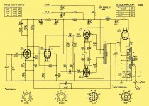
Also I have the actual original schematic of the amplifier (except for the cathode resistor in the phase inverter is 56k ohm). Also if you would not mind to figure out the components values arround the EF86 to change the input sensitivity from 220mV to 1V (thats what most of my quipment does output).
Everything in mine is original except R8 which is 56K in my amplifiers and C13 and C14 which are 470uF
TTG-EL34PP - Tube output transformer [6,6kOhm] 2xEL34 / 2x6L6 Push-pull or similar - Shop Toroidy.pl
Also I have the actual original schematic of the amplifier (except for the cathode resistor in the phase inverter is 56k ohm). Also if you would not mind to figure out the components values arround the EF86 to change the input sensitivity from 220mV to 1V (thats what most of my quipment does output).
Everything in mine is original except R8 which is 56K in my amplifiers and C13 and C14 which are 470uF
Attachments
OK, got it. LTSpice does work out the no signal DC operating conditions but the reason I had to add .ic statements is the DC conditions change as soon as it is outside class A.
nope its this one 🙂
TTG-EL34PP - Tube output transformer [6,6kOhm] 2xEL34 / 2x6L6 Push-pull or similar - Shop Toroidy.pl
Also I have the actual original schematic of the amplifier (except for the cathode resistor in the phase inverter is 56k ohm). Also if you would not mind to figure out the components values arround the EF86 to change the input sensitivity from 220mV to 1V (thats what most of my quipment does output).
Everything in mine is original except R8 which is 56K in my amplifiers and C13 and C14 which are 470uF
I will need gain and phase plot for the test circuit - your speaker is 8R.
I will need gain and phase plot for the test circuit - your speaker is 8R.
copy that if you could give some guidance what to measure where? (Which pins of tube and wherer to put scopes and stuff).
Just the transformer only - see post #224
alrighty. I currently dont have a signal gen available (not one that would be usefll at any rate for this). I hope this next week I can get in school to just measure this.
I’ve “Heath Robinson’d” something together that appears to be working in order to make these measurements. Do you need from 1KHz up only? One minor difference will be that the output from my signal generator only goes up to 7Vrms / 20Vp-p.If you wish for me to try and get some NFB values for you I need an accurate model of the UA21 OPT. I would need you to sweep the transformer using the circuit attached with say a 10V input, and measure the ratio of the secondary voltage to the primary voltage with the output connected up for 8R into an 8R load and a source impedance from the signal generator of 4k7. More importantly I need the phase difference between the two traces. This would be for 1,2,5,10,20,30,50,80,100,120,150 KHz spot frequencies - is this possible?
View attachment 847741
The data sheet for the transformer is not going to give the information.
WoW. That's interesting - I don't know how that can be modelled with the normal transformer model. The reversal of the phase response will help in stability.

Without a lot of time this is as close I can get:
.SUBCKT SOWTER_UA21 1 2 3 4 5 6 7 8 9 10 11 12 13
+PARAMS: LPRIM=40 RPRIM=192 RSEC=.05 LLEAK=10m CLEAK=1n RLEAK=15k CPRIM=1.5n LRATIO={1/2500}
* LPRIM IS THE TOTAL PRIMARY L (VARIES WITH MEASUREMENT).
* LLKG IS THE LEAKAGE L (MEASURABLE: CONSISTENT).
* RPRIM IS THE TOTAL PRIMARY R.
* CPRIM IS THE MEASURED PRIMARY CAPACITANCE.
* LRATIO IS THE INDUCTANCE RATIO: (4 OHMS)/(PRIMARY Z).
LS1 1 20 {LLEAK}
CS1 1 20 {CLEAK}
RS1 1 20 {RLEAK}
CPR 20 25 {CPRIM}
LP1 20 21 {LPRIM*.09} ; .7164H ; PRIMARY
RP1 21 2 {RPRIM*.3}
LP2 2 22 {LPRIM*.04} ; .3184H
RP2 22 3 {RPRIM*.2}
LP3 3 23 {LPRIM*.04}
RP3 23 4 {RPRIM*.2}
LP4 4 24 {LPRIM*.09}
RP4 24 25 {RPRIM*.3}
LS2 25 5 {LLEAK}
CS2 25 5 {CLEAK}
RS2 25 5 {RLEAK}
LP5 7 31 {LPRIM*LRATIO}
RP5 31 6 {RSEC}
LP6 9 32 {LPRIM*LRATIO}
RP6 32 8 {RSEC}
LP7 11 33 {LPRIM*LRATIO}
RP7 33 10 {RSEC}
LP8 13 34 {LPRIM*LRATIO}
RP8 34 12 {RSEC}
KALL LP1 LP2 LP3 LP4 LP5 LP6 LP7 LP8 .99995
.ENDS

- Home
- Amplifiers
- Tubes / Valves
- Testing newly built mullard 5-20