It not the final version (for example the EF86 has a bit too much DC current). I think you referring to the cap into the EL34. Its to do with making the LF stable when NFB is applied. Basically you don't want the LF pole of the transformer and the LF pole of the couple cap to be similar. Usually you make the pole into the EL34 higher. You could also make it a lot lower but the grid blocking gets worse. I have the wrong transformer at the moment.
So for the UA21 the LF pole from datasheet is 5Hz - so I would make the coupling into EL34 around 15-20Hz. If you make them the same you will see the closed loop frequency response will have a nasty peak at about 2Hz and may well oscillate - as each pole will produce say 70 deg phase shift near the unity gain point.
So for the UA21 the LF pole from datasheet is 5Hz - so I would make the coupling into EL34 around 15-20Hz. If you make them the same you will see the closed loop frequency response will have a nasty peak at about 2Hz and may well oscillate - as each pole will produce say 70 deg phase shift near the unity gain point.
Last edited:
In fact the audio coupling capacitors are more serious an issue than I had initially thought. Because there will be no negative feedback, LF will run at full gain and will saturate the driver stage.
Yep, at very low frequencies <5Hz you could saturate the driver as the NFB drops off. However the new V2 stage has loads of headroom - and as you suggest we should have a DC blocking cap on the very input which should be at say 10-20Hz or the like. You could go big cap into the EL34 but they will get quite physically big. You also get into worse blocking recovery times (when the grid is driven positive which alters the output bias) that can sound quite bad. What you must not do is place the poles in the same place. There is a solution to this by modifying the NF to introduce a zero to cancel one of the poles.
Last edited:
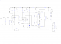
If you wish for me to try and get some NFB values for you I need an accurate model of the UA21 OPT. I would need you to sweep the transformer using the circuit attached with say a 10V input, and measure the ratio of the secondary voltage to the primary voltage with the output connected up for 8R into an 8R load and a source impedance from the signal generator of 4k7. More importantly I need the phase difference between the two traces. This would be for 1,2,5,10,20,30,50,80,100,120,150 KHz spot frequencies - is this possible?

The data sheet for the transformer is not going to give the information.
The data sheet for the transformer is not going to give the information.
I should be able to do this though I currently lack the necessary BNC adapter cable to connect the signal generator to the bare ends off the transformer. I have one in work, which ironically I looked at last Friday thinking “that might be handy.” I might be able to cheat it using bnc to rca adapters.If you wish for me to try and get some NFB values for you I need an accurate model of the UA21 OPT. I would need you to sweep the transformer using the circuit attached with say a 10V input, and measure the ratio of the secondary voltage to the primary voltage with the output connected up for 8R into an 8R load and a source impedance from the signal generator of 4k7. More importantly I need the phase difference between the two traces. This would be for 1,2,5,10,20,30,50,80,100,120,150 KHz spot frequencies - is this possible?
View attachment 847741
The data sheet for the transformer is not going to give the information.
You could go big cap into the EL34 but they will get quite physically big. You also get into worse blocking recovery times (when the grid is driven positive which alters the output bias) that can sound quite bad. What you must not do is place the poles in the same place. There is a solution to this by modifying the NF to introduce a zero to cancel one of the poles.
The additional drive current and headroom, and lower value coupling capacitor will make 'blocking' occur far more easily.
I've now made a full schematic, the turret board layout and the CCS layout. The schematic includes the full power supply as it currently is.
Attachments
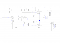
There will be some small component changes due to my incompetence - when you have the transformer gain and phase let me know, your transformer needs a ground on the speaker side. I will send you a ltspice schematic. Things I need to check:
1) Input current through EF86
2) Making C6 10uF by increasing R11
3) NFB component values.
1) Input current through EF86
2) Making C6 10uF by increasing R11
3) NFB component values.

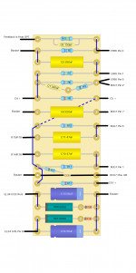
OK spent a bit more time on the simulation we have the correct output transformer but not with the correct HF response.
I've decreased the bias in the EF86 to 1.5ma changed C6 back to 10u by increasing R17 to 10k. I have increased R8 to 100k to stop any HT noise getting in there.
Unfortunately pjl123 comments were correct in that I cannot get LF stability will just the coupling caps to the EL34's - I think this came up much earlier in the post. So I had to add R26 and C13 to cancel out some of the double pole with a zero. This sorts out the LF. It also brings the gain up a bit so .8v peak will generate full output. This was getting a bit low! Sorry that will need an addition to your turret board.
The NFB components will have to wait until you have done the measurement. D2 and D3 are 5W devices.
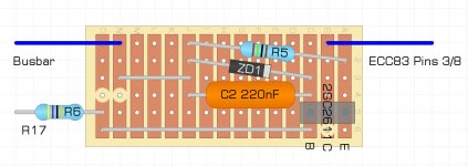
Noted. Luckily, I've not started work on it yet as I've been waiting for some bits to arrive. It's also helped me spot an error on the turret board as there are 6 turrets before the EF86 step network and I'd only put 5. With C13 100uF cap, what voltage rating will it need to cover? To my knowledge, I've not got any 100uF axial parts but I should have some radials in at least 25V. Also unsure if I have a 1.2K resistor, I'll need to do some digging to find out for sure. I've definitely got 1K and 1K5. Everything else I should have.View attachment 847874
OK spent a bit more time on the simulation we have the correct output transformer but not with the correct HF response.
I've decreased the bias in the EF86 to 1.5ma changed C6 back to 10u by increasing R17 to 10k. I have increased R8 to 100k to stop any HT noise getting in there.
Unfortunately pjl123 comments were correct in that I cannot get LF stability will just the coupling caps to the EL34's - I think this came up much earlier in the post. So I had to add R26 and C13 to cancel out some of the double pole with a zero. This sorts out the LF. It also brings the gain up a bit so .8v peak will generate full output. This was getting a bit low! Sorry that will need an addition to your turret board.
The NFB components will have to wait until you have done the measurement. D2 and D3 are 5W devices.
EDIT, found I've got some nichicon PX, muse ES and panasonic FM 100uF 25V caps that I can use and a decent collection of 1.2K 1/2W metal film resistors.
Attachments
Last edited:
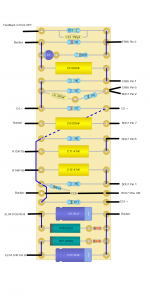
100uF very low voltage as there's only 2v there. I did change a couple of other values (around the EF86, input coupling cap, power supply dropper resistor etc) so it would be worth rechecking before you build. Your ground on the OPT transformer output is missing. Some of the plate resistors and supply droppers will need to be 1W or 2W as well as the cathode resistors on the EL34's. If diyaudio valve expert could just cast their eye over it that would be really great.
The ground of the HT CT and heater CT should be taken back directly to C2 and then C2 should become your amp ground. This ensures the rectifier currents do not enter your signal ground.
The ground of the HT CT and heater CT should be taken back directly to C2 and then C2 should become your amp ground. This ensures the rectifier currents do not enter your signal ground.
Last edited:
I thought that would be the case with the voltage rating for that cap but preferred to make certain. Good spot on the OPT ground in the schematic. Basically all the resistors in this amp are 2W BC PR02's and Dale CMF. There is a random assortment of whatever I can find in my box of bits for values I didn't buy. Judging what their power rating is has become difficult as the size of high wattage resistors has come down so much. I've hedged my bets that the majority of what I have is 0.5W and 1W.100uF very low voltage as there's only 2v there. I did change a couple of other values (around the EF86, input coupling cap, power supply dropper resistor etc) so it would be worth rechecking before you build. Your ground on the OPT transformer output is missing. Some of the plate resistors and supply droppers will need to be 1W or 2W as well as the cathode resistors on the EL34's. If diyaudio valve expert could just cast their eye over it that would be really great.
The ground of the HT CT and heater CT should be taken back directly to C2 and then C2 should become your amp ground. This ensures the rectifier currents do not enter your signal ground.
One thing I've noticed whilst going over the schematic that seems a bit odd compared with most other designs. The resistor between the grids of 6CG7 is 470K (R13 in my schematic above) where the norm on everything seems to be 1Meg. What effect does the lower value have?
I assume that the grid stoppers on the EL34's are 10K which seems high. I guess this is to bring the low pass filter effect down to try and combat some of the HF oscillation issues?
I assume that the grid stoppers on the EL34's are 10K which seems high. I guess this is to bring the low pass filter effect down to try and combat some of the HF oscillation issues?
One thing I've noticed whilst going over the schematic that seems a bit odd compared with most other designs. The resistor between the grids of 6CG7 is 470K (R13 in my schematic above) where the norm on everything seems to be 1Meg. What effect does the lower value have?
I assume that the grid stoppers on the EL34's are 10K which seems high. I guess this is to bring the low pass filter effect down to try and combat some of the HF oscillation issues?
The 470k is not critical - I just dropped it so that the grid leakage into the 6CG7 does not unbalance the plates as much. Anything from 220k upwards will work - it will only affect the size of the cap to ground.
The grid stoppers are bigger to improve the blocking distortion. Basically if the grid of the EL34 goes positive it will conduct. Over a number of cycles this will charge the coupling caps into the EL34 and bias the EL34 out of conduction. The increase of grid resistors reduces this current and therefore reduces the problem. It quite objectionable audibly. The reduction of the plate resistors means the LTP can drive much harder, so the grid resistors have been increased. Theres only about 10p of capacitance to drive.
The HF we will sort out when you have a transformer plot. When you test for stability I would suggest a 1KHz square wave rather then 15KHz so we don't unbalance the driver stage due to non-linearities on the fast edge (there are less of them).
Last edited:
Thanks for the clarification on that. I’ve made one discovery whilst taking things apart on the turret board, the cap I thought was 220nF was in fact 22nF which is an error that has been present right from the first build using the standard Mullard design. Wish I could blame that on RS but I definitely ordered the wrong ones back in February.
The general rule is:
If you want to prevent any grid current, turn the volume down a little.
Now if the amplifier is a different one, which is "properly designed" to intentionally draw grid current, such as AB2, etc., then by all means . . . turn the volume up.
Where "properly designed", does not include RC coupling to the output stage.
Out of interest, what would the effect of having too small a capacitor on the link between the grids of the PI to ground have? (my oops moment of discovering I've been using 22nF instead of 220nF without realising)
Also, what voltage should I be seeing across the Base of the transistor used in the CCS and consequently the 220nF capacitor? I've been looking at what I have that is compact enough to fit on the veroboard. I've got 220nF 100V or 330nF 250V.
Also, what voltage should I be seeing across the Base of the transistor used in the CCS and consequently the 220nF capacitor? I've been looking at what I have that is compact enough to fit on the veroboard. I've got 220nF 100V or 330nF 250V.
Kei,
Return the center tap of the 410v-0-410V transformer directly to C2.
Only then, return from there to the amp's central ground. Keep those transient charging currents local. And do not connect the filament center taps to the B+ center tap, instead return them to the amp's central ground.
Otherwise, the schematic as drawn will have the C2 ripple currents make a voltage drop that is put onto the filament supply center taps. And that would put noisy rectifier transients onto the filaments of V1 and V2a and V2B.
V1 cathode is most sensitive because it is the first gain stage. Any capacitance and any resistance between the filament and the cathode will be amplified by the circuit voltage gain of that stage.
V2a and V2B will likewise get transient signals, but at least there is less gain, and it is a common mode signal that will tend to cancel somewhat (but will put that common mode signal onto the output stages.
I looked at the input pentode cathode's circuit, Post # 230, might not be right.
And the input pentode cathode's circuit, Post # 227 might be OK.
I am used to seeing a self bias resistor and parallel bypass cap from the cathode, and then from there to a resistor to ground; with the feedback resistor and capacitor connected to the junction of the 3 parts in the cathode circuit.
Your post # 27 found a good way to eliminate the bypass capacitor, as long as the other resistance values, and the small feedback capacitor are correct.
"Any single change in a circuit usually requires three more additional changes" - me
Last edited:
Yep both CT's should go back to C2 separately agreed badly explained by me.
I think with the cathode circuit you are suggesting putting the 100uF in the feedback path as a coupling cap with a resistor across it. I was trying to avoid another LF pole in the loop which will push the phase lag even further into instability. Instead the cap is connected to ground to add zero which cancels one of the existing poles in the loop - I will recheck.
The 220nF across the zener has the zener voltage (6v8) across it.
Last edited:


I send some closed loop plot (measured on plate of LPT) for the different LF compensation schemes. The first three have to cap to the cathode and the second four the cap to ground. They have different cap values. As can been seen the cap on the cathode does need to go to ground to do the right thing - although a cap in the the third picture down is also helping. Trouble is loop compensation is non trivial.
Last edited:
- Home
- Amplifiers
- Tubes / Valves
- Testing newly built mullard 5-20