It is good enough, I think. The level of your mains noise node is of such low level, that it won't be easy to lower it.
Now that I better understand how to use ARTA I'm getting similar results to others.
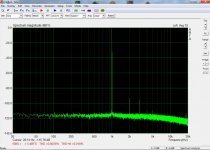
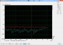
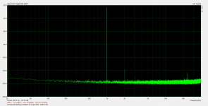
I just need to see if I can reduce the 15dB mains bump. Interface is currently powered from a computer USB port. I thought earthing the switch shaft and mu metal shielding top and bottom would fix that.
View attachment 728127
Try powering it with an external USB battery. That would completely isolate you from the mains.
Your soundcard is powered by the PC.
Your interface connected to the soundcard is powered by the USB port - did you use the USB port ground wire too? If so, a ground loop very likely exists between the ground of the PCI slot and ground of the USB port. On the other hand there is no 50Hz activity on the PC motherboard which could create 50Hz noise in this ground loop.
Did you try Juli's balanced inputs? They are nothing special but should suffice with this type of common noise.
Hi dch53
Your LOOPBACK test don’t have 50Hz signal. Try an input isolation transformer to the DUT. If the 50Hz signal is gone, it may have extra harmonics from a poor isolation TX then you know that you need a better TX or balanced input to feed the DUT.
Duke
Your LOOPBACK test don’t have 50Hz signal. Try an input isolation transformer to the DUT. If the 50Hz signal is gone, it may have extra harmonics from a poor isolation TX then you know that you need a better TX or balanced input to feed the DUT.
Duke
With respect to Duke's comment - were the original spectrum plots showing no mains signal obtained using the same test setup as the latest plot showing some mains signal, or ?
Thanks for all the responses.
Same setup but different level. The original spectrum plot in #796 was a much higher level, possibly too high a level. Hence the better SNR but poor THD.
As noted by Vovk Z in #801 it's probably good enough (I'm testing valve amplifiers) and will be difficult to remove. I will try improving the shielding inside the box. I'll try a battery too but an earlier post didn't find that helpful.
I'm using the balanced outputs of the Juli@ sound card.
Pete Millet indicates there should be no noise/hum entry via the use of 5V from a PC USB. So you may want to try better loopback and signal connection cables, or cover/enclose that entire region in a shield (eg. I've used BBQ foil trays clipped together with holes punched through for cables and probes etc). And switch off all mains cables and lights (especially desk LED lights) within cooee.
As phofman indicates, it could also be worthwhile using a 5V supply coming from the soundcard itself (depending on what voltage rails the soundcard uses, although it should have a local 5V rail due to the midi capability) to a dummy USB port located next to the soundcard external connections end, or just a twisted wire connection to a plug for the interface J3 5V power socket. I guess the risk is if the 5V rail is accidentally shorted, it may damage the soundcard. But could be worth trying to see if there is any influence.
And of course you still have to check what happens with real world earth loops when connecting to DUTs that are mains powered.
I'm using the balanced outputs of the Juli@ sound card.
Outputs or inputs?
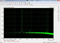
Better shielding did the trick!
It must have been picking up the mains from the environment.
I have thin sheets of mu metal stuck to the inside of the top, bottom and sides of the case. I linked the side pieces to the top and bottom sheets with blobs of solder and earthed them which I hadn't done before.
The mains hump has disappeared altogether.
This is without the higher performance components. I included these when I ordered all the parts so I might as well fit them.
Well done. I did not know your enclosure was not fully shielded.
For shielding smaller non-conducting enclosures or compartments a solderable copper tape has been of great help to me 50mm x 3m EMI Copper Foil Shielding Tape Conductive Self Adhesive Barrier Guitar | eBay
For shielding smaller non-conducting enclosures or compartments a solderable copper tape has been of great help to me 50mm x 3m EMI Copper Foil Shielding Tape Conductive Self Adhesive Barrier Guitar | eBay
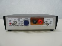
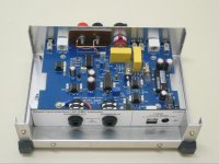
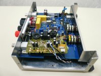
Here is how I built mine. I used a generic cheap metal box modified to the rear to fit the pcb. I built it with the THAT chips and the light bulbs but sans the LCD. I put connectors for my DMM for this job. I attach loop measurements with a behringer UCA 202 usb soundcard. The performance is primarily compromised by the soundcard. I'm making some thoughts to transplant it into the interface box, bypass its analog in/output and connect the chip directly to to the interface making it a stand alone device.
Attachments
Thanks Magic. I included the THAT parts and lamps in my component buy so I can go down that route.
I was confused by your first trace with the fundamental at -1.5dBFS. I realised there must be something wrong with my calibration because I can never get anything like that. Even -3dB produces serious clipping according to Time Record.
Paragraph 1.5.2 Calibration of Soundcard Input Channels has never made sense to me. Step 3 says "Press the button 'Generate sine (400Hz)' and monitor the input level at bottom peak-meters..." When I do that, the peak-metres don't register anything.
I've just left input calibration unchanged from the value resulting from the output calibration. If I set the Generator to -30dB (240mV) and use the 200mV scale on the soundcard interface I get -28.3dBFS.
I'll have to learn how to use STEPS too.
I started from the same level as you about a year ago and still learning so, I can only describe what I've found hoping it will help. It seems you have digital clipping, you will know how ugly that is when you feed real music to your speakers under this condition. Anyway, you can go to your soundcard control panel and see if you can adjust line in levels - you should. Set out level to max and adjust input until you get the best results for calibration and measurements. To give you an example, in my soundcard, the input level slider has a range from 0 to 100 and I had to take it down to 3. Once you get the calibration right, STEPS is easy to use.
Interesting that the 50Hz peak was not eliminated by the balanced input. Any reason for that?
Not to beat my own drum, but a SilentSwitcher from the diyaudio store, fed by a Powerbank, will completely cure that.
Jan
Jan: Does that mean the peak is caused by 50Hz noise in power supply? Or 50Hz noise in the ground loop caused by the way the device is powered?
Or perhaps induced into the tool from the outside?
IMO the easiest way would be trying to power the tool from the soundcard itself. Power lines are easily available in Juli (pinout e.g. hifi.slovanet.sk :: Zobrazi? t?mu - Anal?gov? ?as? ESI Juli@ + I2S )
Or perhaps induced into the tool from the outside?
IMO the easiest way would be trying to power the tool from the soundcard itself. Power lines are easily available in Juli (pinout e.g. hifi.slovanet.sk :: Zobrazi? t?mu - Anal?gov? ?as? ESI Juli@ + I2S )
Here is how I built mine. I used a generic cheap metal box modified to the rear to fit the pcb. I built it with the THAT chips and the light bulbs but sans the LCD. I put connectors for my DMM for this job. I attach loop measurements with a behringer UCA 202 usb soundcard. The performance is primarily compromised by the soundcard. I'm making some thoughts to transplant it into the interface box, bypass its analog in/output and connect the chip directly to to the interface making it a stand alone device.
In case anyone would be interested, I finally did that. Performance is slightly improved and it's now very handy to use. One usb cable plug n' play, no drivers required.
Attachments
Incorporating the soundcard into the box is a great idea. What voltage levels are you putting into the interface and what setting are you using? I suspect you're using higher levels than I am.
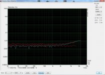
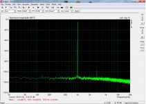
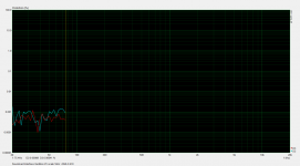
Attached are my best results with the standard ICs and shielded box. Best results are on the 2V scale.
You'll noticed that the distortion results stop at 75.4Hz. This is a problem I'm having with STEPS: the sweep terminates after a random number of steps. I have to click "Stop" to regain control of the app. I posted a question on the ARTA thread but I still have the problem.
Attachments
As already said I'm not a specialist myself but willing to help this is what I've done: PC interface set to 2V range, soundcard output level to max (100/100), input level quite low (2/100). But this setup may not apply to other soundcards. I found that working during the calibration procedure, where I suspect you may have done something wrong. Better try to calibrate without the PC interface in the test rig and follow the instructions to the letter. Remember to take AC measurements with your DMM and of course you will need to do calibration separately for STEPS. Also at steps check single channel level at measurement setup.
- Home
- Design & Build
- Equipment & Tools
- Test & Measurement interface for Soundcard