Mine is all finished now.
When trying to zero the DC offset I can't get any lower than 1,2mV with R25 turned fully CW.
Is this OK or do I have to check something?
Walter
When trying to zero the DC offset I can't get any lower than 1,2mV with R25 turned fully CW.
Is this OK or do I have to check something?
Walter
Mine is all finished now.
When trying to zero the DC offset I can't get any lower than 1,2mV with R25 turned fully CW.
Is this OK or do I have to check something?
Walter
One of the two units I built also will only zero to 1.2mV - the other to 0.2mV. As far as I could tell the meter circuit is picking up some noise (above audio frequency) from the DC/DC converter, and is not real DC offset.
This doesn't seem to affect anything I've used it for, so I never bothered to track it down. So I would say it's OK.
Pete
Well, I'm almost done, just need to pluck up courage to power it up, oh and buy a sound card to start testing.
I have earthed the switch shaft but not attempted any shielding yet, but I do have a roll of copper tape at the ready.
Andrew
I have earthed the switch shaft but not attempted any shielding yet, but I do have a roll of copper tape at the ready.
Andrew

Did you get luck and get it to zero, or did you have to make some mods.
How is the noise floor?
Looks good. VERY nice piece of equipment to have around
How is the noise floor?
Looks good. VERY nice piece of equipment to have around
I put the input switch to ground (as in not floating) plugged in an old BNC and then shorted the other ends of the cable with a test clip, it settled about 0.3mV so I tweaked R25 and got it to 0.0mV, I must be lucky, I guess.
It ran fine off a USB, its an older MB tho'....
Anyone got any ideas, did I just get lucky? I'm just happy it seemed to work, or perhaps it isn't.......
I need to go back over the circuit and see.....
I did get my four year to old match all the resistors on a decent DMM, perhaps that's what did it..hah, well he had a wail of a time 😉 so much so, in fact, I'm thinking of getting some of those educational kits for us to build together...
My next step is to order up a ESI Juli@, when that arrives I'll report back like the other guys have with some graphs.
I reckon I'll end up shielding the box.
I used the THAT Corp receiver and driver chips and the LME op amp, everything else is stock apart from the input caps which are as mentioned in a previous post.
Andrew
Hi Walter, no I just turned the pot labeled R25 until it zero'd, no extra magic....sorry I can't be of more help 🙁
Just a thought, did you set the switch SW2 to ground when you tried to zero? I assume that's the right thing to do...it seemed to make sense to me, anyway.
Andrew
Andrew
Bummer, must be the superb matching job of your toddler than 😀
Yes it was switched to ground when I did the regulation.
Walter
Yes it was switched to ground when I did the regulation.
Walter
Ordered a new DC-DC convertor just to see if I maybe can get the DC offset a bit lower.
Regards
Regards
What sort of behaviour should I expect when using a floating sig gen to calibrate the SC Interface?
Basically, I have been trying calibrate the meter using a sine wave from a sig gen set against a second 'known' meter. The sig gen is directly connected to the SC Interfaces' Input with a BNC lead, the sig gen has a floating output.
On the 200mV range, both floating and grounded, I get a sensible reading, its a little higher on the floating setting. However, when I move to the 2v range I only get a sensible reading when the input is grounded. When it floats I get an over-reading (the meter says 1 on the leftmost digit all others are blank). I measured the input to the meter chip at about 600mV DC (measuring pin 1 on the AD536 chip).
I wasn't expecting this, have a bug or am I misunderstanding what should happen in this instance, i.e two floating devices? At this junture in the morning its quite possible I'm being dense.
I should report that the input capacitors I used (they fit fine by the way) the output is 0.3db down at 10Hz.
Andrew
Last edited:
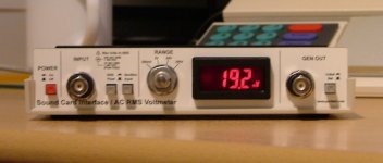
Well it goes 🙂
I ended up shielding the upper and lower case with copper tape and placing a grounding lug on the back panel just to the left side of the TRS jacks. I then connected both upper and lower shields and shaft of SW4 to the ground lug.
With this separately grounded to earth I get very reasonable results and no sign of 50Hz 🙂
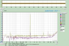
TDH = 0.0005%
Not quite as good as some others, but not bad, that at 20hz to 90kHz with the resolution set to just below 1Hz.
There's some artifacts creeping in at 30-ish Hz and then closer to 15 and 20kHz. I intended trying again to see if these were in the environment or my s/w configuration.
Thanks Pete a very enjoyable project and I am looking forward to putting it to use.
Andrew
I ended up shielding the upper and lower case with copper tape and placing a grounding lug on the back panel just to the left side of the TRS jacks. I then connected both upper and lower shields and shaft of SW4 to the ground lug.
With this separately grounded to earth I get very reasonable results and no sign of 50Hz 🙂
TDH = 0.0005%
Not quite as good as some others, but not bad, that at 20hz to 90kHz with the resolution set to just below 1Hz.
There's some artifacts creeping in at 30-ish Hz and then closer to 15 and 20kHz. I intended trying again to see if these were in the environment or my s/w configuration.
Thanks Pete a very enjoyable project and I am looking forward to putting it to use.
Andrew
Attachments
I am building this interesting interface but I am not able to find a part of it.
Or better Digi-key is out of stock and they have not a date for the connector SAM1224-15-ND ( Samtek SSQ-115-02-T-D-RA ); they say that Samtek don't know when they will can deliver them ...
Somebody know where to buy it or if exists something of equivalent to replace it?
Thanks and regards.
Marco
Or better Digi-key is out of stock and they have not a date for the connector SAM1224-15-ND ( Samtek SSQ-115-02-T-D-RA ); they say that Samtek don't know when they will can deliver them ...
Somebody know where to buy it or if exists something of equivalent to replace it?
Thanks and regards.
Marco
Hi Marco,
I found it at a local store: it had more pins, but cutting out the excess holes solved the problem.
Ciao,
Claudio
I found it at a local store: it had more pins, but cutting out the excess holes solved the problem.
Ciao,
Claudio
Hi Claudio,
Thanks for your answer, infact searching carefully I have found at Distrelec the part "121600" that is 36x2, more long like you say, but almost identical ...
Cutting it, probably I should have two of what I need 🙂
Marco
Thanks for your answer, infact searching carefully I have found at Distrelec the part "121600" that is 36x2, more long like you say, but almost identical ...
Cutting it, probably I should have two of what I need 🙂
Marco
Not very cheap, at Distrelec.
When cutting, leave a row in excess on each side, for safety.
The extra space won't be a problem when placing the connector in the case.
Claudio
When cutting, leave a row in excess on each side, for safety.
The extra space won't be a problem when placing the connector in the case.
Claudio
- Home
- Design & Build
- Equipment & Tools
- Test & Measurement interface for Soundcard