Yeah, exactly what I did other times for similar problems ...
Do you know where buy it at better price?
Marco
Do you know where buy it at better price?
Marco
At the time I build the Jig, I found that connector in my town local store. I paid a couple of euro for a 2x50 pins.
Also some computer cables could be adapted, the ones used to connect Hard Disk, but lot of work is needed and I am not sure if it is worth.
Claudio
Also some computer cables could be adapted, the ones used to connect Hard Disk, but lot of work is needed and I am not sure if it is worth.
Claudio
Yes, floppy disk cable and connector is 34 pins ...
I have also found ASSMANN A-BL254-DA-xxxD series.
Thanks for your advises.
Marco
I have also found ASSMANN A-BL254-DA-xxxD series.
Thanks for your advises.
Marco
Just wondering ... (without re-reading this entire thread) ...: Has anyone tried to evaluate any of the standalone (non-PCI or PCIe) sound cards with the gadget?
There was some work on one of the EMU cards, there's a couple of threads on this forum about it.
I would love to hear some input on this subject, what is the best sound card?
I made some interesting findings last night that fit nicely with this question.
What I discovered was that there is a distinct difference between the sound card outputs when testing on monitor/loopback. I noticed this when generating a measurement baseline which I always do before hooking up the amp under test.
One output has more higher level harmonics on it.
I use a ESI PCI card, by its nature a PCi card is on a very small PCB, and all teh outputs are very close together.
I do wonder if there's some crosstalk? Will an external box do a better job as everything is less crammed in?
Now this difference doesn't bother me as I can only use one channel at a time for measurement but it is interesting none the less since it is the output channel farthest from the sound card's input channel that is markedly better and matches the images I posted earlier.
So, if you can imagine I am using sockets 1 and 4 on the card for in and out left to right, so red channel out and white channel in - this nets maximum physical separation and the best results.
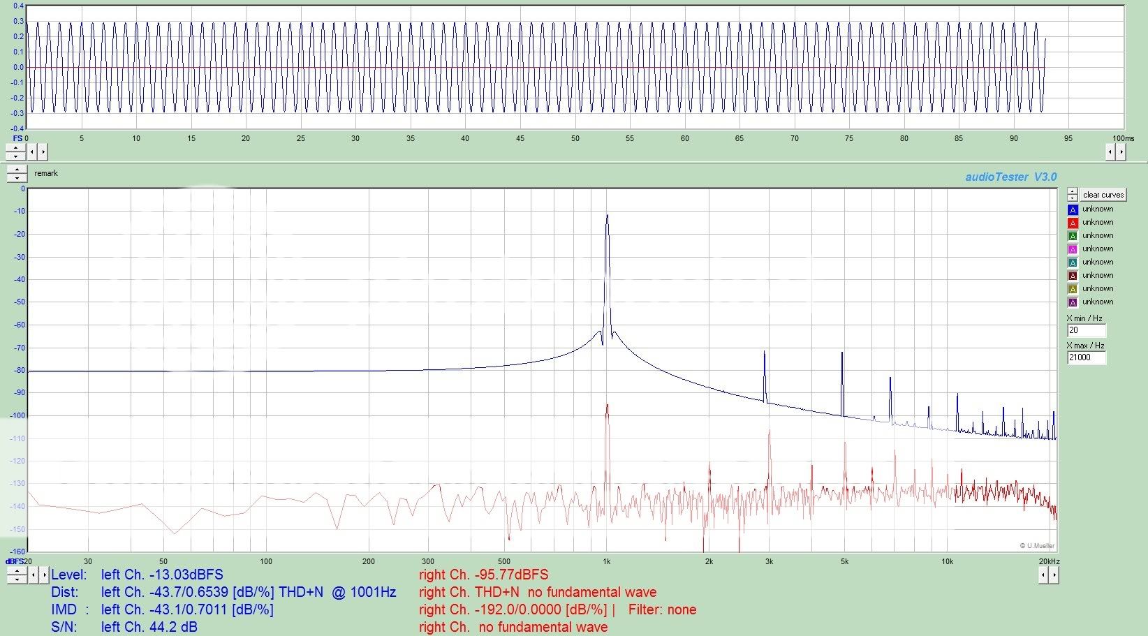
Even better results by far, however, are with the sound cards generator turned off completely and using the generator signal from a distortion analyser.
At that point the FFT reads -115db/0.0002% THD @ 2v RMS, isn't that almost as good as £20K's worth of Audio Precision, at least on FFT terms?
I suspect, I am seeing crosstalk between the cards input and outputs.
Of course, could it be the generator in my analyser is just better than the one in sound card?
Andrew
I would love to hear some input on this subject, what is the best sound card?
I made some interesting findings last night that fit nicely with this question.
What I discovered was that there is a distinct difference between the sound card outputs when testing on monitor/loopback. I noticed this when generating a measurement baseline which I always do before hooking up the amp under test.
One output has more higher level harmonics on it.
I use a ESI PCI card, by its nature a PCi card is on a very small PCB, and all teh outputs are very close together.
I do wonder if there's some crosstalk? Will an external box do a better job as everything is less crammed in?
Now this difference doesn't bother me as I can only use one channel at a time for measurement but it is interesting none the less since it is the output channel farthest from the sound card's input channel that is markedly better and matches the images I posted earlier.
So, if you can imagine I am using sockets 1 and 4 on the card for in and out left to right, so red channel out and white channel in - this nets maximum physical separation and the best results.
Even better results by far, however, are with the sound cards generator turned off completely and using the generator signal from a distortion analyser.
At that point the FFT reads -115db/0.0002% THD @ 2v RMS, isn't that almost as good as £20K's worth of Audio Precision, at least on FFT terms?
I suspect, I am seeing crosstalk between the cards input and outputs.
Of course, could it be the generator in my analyser is just better than the one in sound card?
Andrew
Attachments
Of course, could it be the generator in my analyser is just better than the one in sound card?
Andrew
In the little bit of time I have put in with measurements, I have found this to be the case. My Saffire was pretty bad, a lot of improvement with MAudio Profire 610, but still, the analog output needs to be turned down to a 'sweet spot' where is produces the least distortion.
My best results are coming from using SPDIF output to a Behringer DCX2496 transformer coupled output. The sound card inputs appear better than the outputs.
... I would love to hear some input on this subject, what is the best sound card? ...
What I discovered was that there is a distinct difference between the sound card outputs when testing on monitor/loopback. I noticed this when generating a measurement baseline which I always do before hooking up the amp under test.
One output has more higher level harmonics on it.
I use a ESI PCI card, by its nature a PCi card is on a very small PCB, and all teh outputs are very close together. ...
Guessing 😕 :
* Electronic and/or physical distance from output (L) verses output (R) from the PC's power supply are the same? Different?
* PCI Card ground plane orientation as shield from PC processor(s) noise for output (L) verses output (R) is the same? Different? (Or does the PCI Card even have a ground plane or other shielding?)
... I do wonder if there's some crosstalk? Will an external box do a better job as everything is less crammed in?
Now this difference doesn't bother me as I can only use one channel at a time for measurement but it is interesting none the less since it is the output channel farthest from the sound card's input channel that is markedly better and matches the images I posted earlier.
So, if you can imagine I am using sockets 1 and 4 on the card for in and out left to right, so red channel out and white channel in - this nets maximum physical separation and the best results. ...
Ah Ha! ... Eureka ...
... Even better results by far, however, are with the sound cards generator turned off completely and using the generator signal from a distortion analyzer. ...
Even more crosstalk potential if the onboard sig. generator outputs to all ports simultaneously ... The onboard sig. generator may not be very well thought out and an added nuisance. (Could it be defeated entirely, permanently? It may be adding stray capacitance, even when defeated.)
At that point the FFT reads -115db/0.0002% THD @ 2v RMS, isn't that almost as good as £20K's worth of Audio Precision, at least on FFT terms?
I suspect, I am seeing crosstalk between the cards input and outputs.
Of course, could it be the generator in my analyser is just better than the one in sound card? ... Andrew
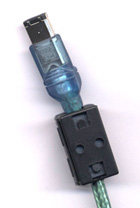
Mmmmm ... As for external sound cards, separation from the PC's switching supply is probably a significant plus, even if bus powered through a USB or FireWire connection. I can't find much online about Power Supply Rejection on stand alone sound cards (= PSRR at the chip level), but intuitively would imagine that it would be better on a longer cable than not ... and the inclusion of RF ferrite lugs might also be a plus.
Last edited:
Please help - high distortion
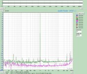
I have the PMillet tester, an EMU 1212m card and a capable dual core machine running Windows 7 with 4GB RAM. I am running a licensed copy of AudioTester 3.0c. Left channel Input only - but some garbage is showing up in the right channel - no idea why. Everything LEFT is panned LEFT. I get no response in the RIGHT channel from PatchMix - yet it appears in AudioTester.
I cannot achieve low distortion < 0.6%! Not even through loopback. It just looks awful. I have played with the settings in PatchMix, followed various guides in this thread and on the web - and still no joy! Do you think I have a faulty card? Something else to try? If I turn off the Sound Generator, my noise floor is -130dB - just fine for me.
Also, I tried to do the calibration with a separate audio generator that can output +/-15V (pk-pk). However, when I try to use the PMillet tester, I can never achieve max input because it overloads the front end before I get to about 40% in Audiotester. I am forced to drive the 1212m directly using an unbalanced source, monitoring the RMS value on an HP 3400A. I am not confident that I am getting accurate calibration.
And one more thing...when I run THD power tests, I get two warnings about high levels (expected), but then nothing happens. The test does not start. What the heck is going on?
Please help soon, I have a customer waiting for his design and I can't give him accurate THD levels.
EDIT: I just unplugged everything from the soundcard and I get the same results. Someone please tell me - step by step - how to configure this stupid PatchMix so it works. I'm on a hard deadline!
Last edited:
I would love to hear some input on this subject, what is the best sound card?
Andrew
This card is quite good, but you may have found the thread already:
http://www.diyaudio.com/forums/equi...ject-audio-measurements-tool.html#post2072409
I don't know PatchMix, but I do know that you've got a little crosstalk (really, it's not bad at all!) and that there's something interrupting the channel you're testing. What window/apodization are you using?
Just for grins, change the test frequency slightly. 998Hz, for example.
Just for grins, change the test frequency slightly. 998Hz, for example.
Heh.
Well, after blowing all that hot air - I fixed it. 😱 I simply opened a new configuration and started from the basics. I just kept plugging away at different settings until it worked perfectly. I inserted an ASIO send/return...uh....insert into the channel strip.
Anyway - yes, the crosstalk is very low - especially considering that input was open! Now, it's effectively muted so any noise is buried in the noise floor. My operational distortion numbers are now in the 0.005% range, which is perfectly fine for me. My goal was to improve my old system by an order of magnitude and I feel it was successful.
Pete's little test box is a smashing success, in my opinion. I "upgraded" some of the components as outlined in this thread. It likely made little difference, but having a skid of 0.1% resistors in my lab doesn't hurt things. 😀
I'm using the same box, but I soldered sheets of copper tape inside as well as grounded the selector knob shaft and each pushbutton switch case. I don't see ANY 60Hz residuals in my FFT.
EDIT: I believe I was using Hanning window for that screenshot, but it's a trivial affair now. It seems that there was a divergent signal path being fed back. The software itself is rather buggy, too - especially on ASIO drivers. In my case, I found a solution and - at least for now - don't intend to putz with it.
Last edited:
EnvisionAudio: Might want to remove any and all unnecessary PCI cards, then retest.
Oops, Your latest just showed up: Looks like you are already on the right track 😀
Yes, yes, please: AndrewT's request for a step by step to recovery and significant improvements would be very interesting for all of us with any PCI sound cards.
Oops, Your latest just showed up: Looks like you are already on the right track 😀
Yes, yes, please: AndrewT's request for a step by step to recovery and significant improvements would be very interesting for all of us with any PCI sound cards.
Last edited:
EnvisionAudio: Might want to remove any and all unnecessary PCI cards, then retest.
Oops, Your latest just showed up: Looks like you are already on the right track 😀
Yes, yes, please: AndrewT's request for a step by step to recovery and significant improvements would be very interesting for all of us with any PCI sound cards.
There are no other cards in the machine, but that's a great tip.
I wish I knew exactly what I did. If I get a spare moment, I'll try to recreate everything. For the moment, I don't want to disturb it until I'm done with my tests... 🙂
I can't trust the readings I am getting.
I'm using the licensed Audiotester.de and the E-Mu 1212m (with Windows 7 drivers) in a machine running Windows 7 Home Premium. The computer is stripped down to the basics so as not to interfere with the measurement system.
1. The interface I built has a big gap in its attenuation settings. I was trying to test a 100W amplifier - which is ~30V. This is above the 20V setting, so I chose the nest higher...200V. The problem is that the attenuation is so great that the 1212m doesn't tell AudioTester that the signal is large enough. No amount of gain on the 1212m interface gets me adequate input levels.
2. I am forced to calibrate the sound card without the Interface. An external input signal (~15V peak) is never high enough with the interface to calibrate AudioTester's max reading...
3. The RMS meter, though calibrated against an HP 3400A, isn't accurate in the 200V range. I measured 29V RMS on my oscilloscope while the Interface read 21V. Of course, being 21V, I couldn't check accuracy on the 20V scale. 🙁
4. Power/THD tests through AudioTester just clip the interface badly. Because the level is too low on the 200V range, I have to perform the test at 20V - a classic catch-22.
So...should I modify it for a 30 and 100V range? Or, should I change the sound card to something else? Any ideas?
Thanks.
Last edited:
I can't trust the readings I am getting.
I'm using the licensed Audiotester.de and the E-Mu 1212m (with Windows 7 drivers) in a machine running Windows 7 Home Premium. The computer is stripped down to the basics so as not to interfere with the measurement system.
1. The interface I built has a big gap in its attenuation settings. I was trying to test a 100W amplifier - which is ~30V. This is above the 20V setting, so I chose the nest higher...200V. The problem is that the attenuation is so great that the 1212m doesn't tell AudioTester that the signal is large enough. No amount of gain on the 1212m interface gets me adequate input levels.
2. I am forced to calibrate the sound card without the Interface. An external input signal (~15V peak) is never high enough with the interface to calibrate AudioTester's max reading...
3. The RMS meter, though calibrated against an HP 3400A, isn't accurate in the 200V range. I measured 29V RMS on my oscilloscope while the Interface read 21V. Of course, being 21V, I couldn't check accuracy on the 20V scale. 🙁
4. Power/THD tests through AudioTester just clip the interface badly. Because the level is too low on the 200V range, I have to perform the test at 20V - a classic catch-22.
So...should I modify it for a 30 and 100V range? Or, should I change the sound card to something else? Any ideas?
Thanks.
Have you run the amp at less than full output, say 18Vrms using the 20v scale? I use the sound card GUI volume control to set the card output voltage. I've been testing my amp using the 20v scale, but, it also works with the 200v scale, just jumps up the noise floor by about 10db (attenuation resistor noise?).
I use the juli@ card and AudioTester.
Ken
Yes, but I want to measure THD/Power. It's fine until the amplifier is driven to high output, but the interface is clipping long before that.
The 200V scale attenuates the signal so much that the Patchmix (1212m GUI) can't give me enough gain to register in AudioTester. Like I said, Catch-22.
1212M FOR SALE. Make me an offer!! 😀
I don't know if it's your sound card. As I said, I haven't had the issue of the of switching between different levels of 2, 20 and 200v scales. In all cases, the signal shows up in AudioTester. I would look at the sound card interface (PMillet device) to make sure that there isn't something wrong with the the 200v circuit, wrong resistor values, cold solder joint ect. Put a signal into it and a voltage meter on the output, you should see signal. I forget what resistor values he used, but, they are there on the schematic, figure out the attenuation and see if the applied signal is adjusted accordingly.
As an aside, I have never gotten the THD/Power plot to work. More of a AudioTester problem and obtuse instructions. Can't figure out what value to set in the AudioTester parameters to get a full plot. If you get the THD/power to work, maybe you can post instructions.
Ken
The Interface is 100%.

I didn't mean to imply that the 200V scale doesn't work - it just attenuates the signal more than I can compensate with PatchMix to get AudioTester to see the initial signal in THD/Power (if it worked). I can start in the 20V scale and click over to 200V, but I'd rather not.
I was wondering about the veracity of the Power/THD mode. AudioTester screens make no sense in the THD/Power tests. The Y axis is labeled %, but the digits are -140 to 0 while the X axis in mV That makes no sense. I guess I'll have to buy another test suite. Any suggestions?
2, 20, 200 are very big jumps for max signal adjustment.
That's why you see, 1, 2, 5, 10 on oscilloscopes and other measuring apparatus. Less seen is 1, 3, 10.
You can easily add a pot to the signal that is a bit too high. But, would you need a balanced pot to allow the card to output and input balanced signals? You are using balanced throughout the test arrangement?
- Home
- Design & Build
- Equipment & Tools
- Test & Measurement interface for Soundcard