More about Murata DC-DC converter startup
I did some research on the Murata site and came up with this app note:
http://www.murata-ps.com/data/apnotes/dcan-58.pdf
See section 6 for an explanation of what is probably happening re:latch-up. it talks about converter startup failure if output capacitance is too high, caused by the converter going into over current failure mode which causes it to start multiple times. In a current limited environment it just fails to start. Murata characterizes this part in the data sheet with 47uf on each output but does not specify a maximum capacitance as suggested in the app note; however, 680uf on each rail plus another 470uF on the 5v regulator may be too much when working with limited startup current. TI mentions the same kind of behavior in their 2 watt converter data sheets and notes that a LC pi filter is more effective at reducing ripple than adding bulk capacitance. Values around 5uh and 47uF (total; ie 22uf x2) drops ripple some 20db from it's already low value.
The Murata app note also notes some concern about large cap values reducing the phase margin of the converter; but the relatively high ESR of the 330uF caps used here probably prevents that.
I am going to experiment with a pi output filter and reduced input and output capacitance. My goal is to limit startup current to 500ma without increasing ripple voltage. If I can accomplish that I will be more comfortable trying the adapter with a laptop USB power source. If not I guess I will have to scrounge together a desktop.
mark
I guess it won't actually fry the laptop the Murata will just sulk?
On another note I looked into soundcards for laptops, specifically external ones, and it seems that the internal sound card solution in a desktop chassis might actually be a better solution. There's a link further back in this thread on the trials of using a USB device.
I'd be very interested in trying it out if you were able to revise the circuit.
Andrew
Mark, did you also try the start up sequence with SW1 open circuit as there's only half the output capacitance until SW1 is closed?
I guess it won't actually fry the laptop the Murata will just sulk?
Andrew
Yes, I tried with the switch off which isolates not just the second set of 330uf caps but also the 470uf on the output of the 5v regulator - same result.
I did a bit more research and I found that virtually all notebooks have active current limiting. For example, here is a link to a Maxim part designed for this purpose: MAX1607 USB Current-Limited Switch in Pin-Compatible Package - Overview which is a current limited high side MOSFET switch with accurate current limiting and short circuit protection designed for USB applications. This device is configurable but normally runs at a 750ma limit. This makes is highly unlikely that I can get 1.4 amps from my USB port to start this converter.
I am very surprised that no one else has reported this behavior, since Pete has had these in the field for some time; this is a solid, proven design. This leads me to two possibilities: either (a) my Murata converter is unusual or just plain bad, or, (b) no one has tried to use this adapter on a laptop. For the time being I'm going with (a).
I would expect that in a current limited environment, a well designed converter would not lock up and short the power supply; rather I would expect it to just take a little longer to power up. I can't imagine Murata selling a part that fails in a way that is so common in so many designs. In the real world, power supplies are not unlimited. Analog wall warts can handle momentary overloads of 2x rating, but switchers can't. So a 750ma wall wart can't be expected to provide 1.5 amps for more than a couple milliseconds. And the cheap ones can't survive a short to ground. So I suspect my converter is bad in some way.
I am going to order another converter and see if it behaves the same. If it does, it is simple enough to add the Pi filter and I will suggest to Pete that he does the same at the next board spin. But I suspect it won't be necessary.
Off to Mouser to place the order...
The input caps should provide the required current to start the converter. (No open trace?)
Sounds like this converter is bad.. I initially had some problems with mine because of a -15V rail to ground short on the pcb, but once resolved the box runs reliably on USB ports that current limit just above 500mA. No problems with any computer I have tried including my Compaq EVO N610C laptop...
Last edited:
Yes, but normally there is protection to turn off the power switches if the voltage gets too low; Murata does not include that feature. I suspect it comes down to a discrete transistor based (ie, old) design rather than a more modern design with soft start and current limiting built in.
This is only a concern to me because I want to use the sound card interface with a new high end laptop since that's all I have (Toshiba Qosmio 505). Laptops use USB chipsets with integrated power management, which includes a strict limit to current (500ma/5v) on each port. So while lots of you have used this successfully with desktops, which use little if any current limiting on USB, I would be interested if anyone has used this with a reaonably modern laptop, say post 2007. Given that in my testing the Murata "let the smoke out" of a 5v/500ma switching wall wart, I am afraid to try it.
Before I spend $$ on a TI soft start converter or messing with the input and output capacitors, any user history with respect to laptop use would be greatly appreciated. Thanks!
Mark
My first Murata didn't work (got very hot), so I bought another which did work. Dumb luck, I guess. I run my interface from a $5 powered USB hub with a 1A-rated SMPS wall wart. It's plugged in 24/7 and hasn't failed yet.
I have plugged it into my desktop without issue. It's just that the hub offers an extension and is more convenient.
Last edited:
The input caps should provide the required current to start the converter. (No open trace?)
Sounds like this converter is bad.. I initially had some problems with mine because of a -15V rail to ground short on the pcb, but once resolved the box runs reliably on USB ports that current limit just above 500mA. No problems with any computer I have tried including my Compaq EVO N610C laptop...
The input cap just exacerbates it because the oscillator starts around 2.5 volts while the input cap is still charging, so the cap is just another startup load.
I got another Murata yesterday and it behaves the same as the first, so my first one wasn't "bad", it was just... bad 🙁. By design if it does not get enough current its overload "protection" is to hang the oscillator and short the input supply across the IR drop of the transformer primary, which is an ohm or so. I guess the comedian who designed it was hoping there would be a fuse out there... or maybe, a small switching wall wart that acts as a fuse the way mine did. The most infuriating part is that the data sheet and app notes make no reference to any of this nonsense. I am sure I am not the first guy to have run into this - I'm not that smart.
I bit the bullet and tested it with my Qosmio and the BIOS faulted. The Qosmio is only a couple months old and it has the new Intel i7 mobile chipset feature called "sleep and charge". This allows the BIOS to selectively control USB port power via a MOSFET switch, even if the computer is asleep. This is unlike older designs where they just hung the USB power pins on a convenient +5 rail with maybe a polyfuse. Based on my measurements this output is tolerant to overload up to about 750ma continuous or 1 amp/~100msec, then it faults. Not bad considering the USB spec is 500ma.
I ordered another 3 watt isolated converter that is supposed to soft start. It's a Recom REC3-0515DR/H1. It is very difficult to get in qty 1 in the US, but I found one in the UK. It uses the same DIP package as the Murata but a slightly different pinout so with a little creative X-Acto work it should be fine. Glad I socketed the Murata for testing 🙂. .
Parts will be here in a week or so.
Mark
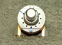
Just to make sure, are these the correct holes to place the pins in (marked with blue stripe)
Regards
My pins are in the same relative position as yours but 180 degrees offset; that is, one pin at 12 o'clock, three spaces clockwise, then the second pin. Since this is being used as a double pole 6 position switch and there are 12 holes your config may still work but I am not completely sure.
Has anyone else done it like this?
Mark
Very odd, I don't know how many Pete has sold, I would guess by this thread a fair few, so, as you say, it seems very odd that only one person has found this problem.I got another Murata yesterday and it behaves the same as the first, so my first one wasn't "bad", it was just... bad 🙁. By design if it does not get enough current its overload "protection" is to hang the oscillator and short the input supply across the IR drop of the transformer primary, which is an ohm or so. I guess the comedian who designed it was hoping there would be a fuse out there... or maybe, a small switching wall wart that acts as a fuse the way mine did. The most infuriating part is that the data sheet and app notes make no reference to any of this nonsense. I am sure I am not the first guy to have run into this - I'm not that smart.
Its confusing, the knurled knob has two valid positions on the shaft, it has two allen nuts, so it does make things harder than they seem.
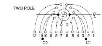
If you orient the shaft as per the attached image, then use a meter to beep you should get contact between C2 and pin 7 and C 1 and pin 1, as far as I can tell that should be the 200mv position. Now place the knob so that the white line is at 200mV, as per image on Pete's site. It will go in another orientation but that would seem to be wrong. Three clicks round should give the 200v position. I didn't check but more beeps should confirm this.
To fix that range of movement, I seem to need to put the first pin at 12 o' clock and then count 3 and insert second pin. All of which would seem to concur with Mark.
Attachments
Very odd, I don't know how many Pete has sold, I would guess by this thread a fair few, so, as you say, it seems very odd that only one person has found this problem.
It does seem odd that nobody else has reported issues. I guess I neglected to say it on the web page (soory!), but I suspected from the beginning that some computers (like laptops with precise current limits) would have an issue supplying the current to start the converter. I actually added the USB power option at the last minute, thinking it could be used instead of a wall wart, at least in most cases.
I believe there are 50 units out there now.
Pete
Its confusing, the knurled knob has two valid positions on the shaft, it has two allen nuts, so it does make things harder than they seem.
If you orient the shaft as per the attached image, then use a meter to beep you should get contact between C2 and pin 7 and C 1 and pin 1, as far as I can tell that should be the 200mv position. Now place the knob so that the white line is at 200mV, as per image on Pete's site. It will go in another orientation but that would seem to be wrong. Three clicks round should give the 200v position. I didn't check but more beeps should confirm this.
To fix that range of movement, I seem to need to put the first pin at 12 o' clock and then count 3 and insert second pin. All of which would seem to concur with Mark.
Got it figured out now, apparently both my solution and AndrewL's work.
Regarding the soundcard:
I can have a great deal on this one, any good?
E-MU Systems - 1212M PCI - PCI Digital Audio System
Regards
Cool, yes, why not? I expect it will work 180 deg the other way too.Got it figured out now, apparently both my solution and AndrewL's work.
Regarding the soundcard:
I can have a great deal on this one, any good?
E-MU Systems - 1212M PCI - PCI Digital Audio System
Regards
On the soundcard, from my research, it would appear the the balanced in/out is a best match for Pete's front-end - if Pete or others could chip in to confirm this, it would help me too.
The candidates seem to be several of the M-Audio cards and some of the EMU's (tho' the EMU's seem to get mixed reviews in at least one thread on here). I looked at the Asus Sonar Essence, which seems to be a very good, but, as far as I can tell, it is single ended only.
Oh, is it worth paying the extra for a the better bandwidth offered by a 24/192 card over a 24/96?
thanks,
Andrew
Last edited:
the brick wall filter of 192kS/s allows upto 95.?kHz frequencies to be gathered....... extra for a the better bandwidth offered by a 24/192 card over a 24/96?
If you were measuring TDH20 then 192kS/s would only gather the first 3 harmonics (40kHz to 80kHz). 96kS/s would gather only the first harmonic (40kHz).
I think this limits distortion measurements to THD5 and below.
How does sampling rate influence FFT?
Last edited:
the brick wall filter of 192kS/s allows upto 95.?kHz frequencies to be gathered.
If you were measuring TDH20 then 192kS/s would only gather the first 3 harmonics (40kHz to 80kHz). 96kS/s would gather only the first harmonic (40kHz).
I think this limits distortion measurements to THD5 and below.
How does sampling rate influence FFT?
I absolutely see where you are coming from, theory (Nyquist-Shannon) would dictate 192Khz would be a better choice. I guess I was wondering how this played out in practice and if it was worth doubling the price of the sound card?
This thread was highlighted earlier by someone, but its probably worth doing it again.
http://www.diyaudio.com/forums/solid-state/137843-issues-emu-tracker-thd-measurements.html
Andrew
http://www.diyaudio.com/forums/solid-state/137843-issues-emu-tracker-thd-measurements.html
Andrew
I've been using the Juli@ card it has balanced out run to 192k and seems to work well with Pete's device.
I'd not run into the Juli@ one, thanks for the pointer. I like the ability to swap between single ended RCA and balanced TRS.
Do your results with it match the success Pete and others have had with the M-Audio 24/96 and 24/192?
Andrew
Do your results with it match the success Pete and others have had with the M-Audio 24/96 and 24/192?
Andrew
Last edited:
I'd not run into the Juli@ one, thanks for the pointer. I like the ability to swap between single ended RCA and balanced TRS.
Do your results with it match the success Pete and others have had with the M-Audio 24/96 and 24/192?
Andrew
Andrew,
My results match and sometimes exceed Pete's results.
Ken
- Home
- Design & Build
- Equipment & Tools
- Test & Measurement interface for Soundcard