....and I can't practice with clock fitting on the old board because I erm....used some bits off it 😱 oops
Pete, are you saying I only need a good 5v supply, an earth connection and an xo plus a coupling cap to the xo ' in ' on the board ?
Can it really be so simple to make ready ?
Yes, it may not be the best implementation though, all depends on the quality of the 5v supply.
Once that's done it's the clock to do - the one thing that makes me nervous.
Not because it's hard to mechanically fit and wire it - I just don't understand which bits to lift or remove.
If you look at the manual the chip has clock in and clock out legs with a small circuit between them. Clock out supplies the voltage and clock in gets the clock output. It's not strictly necessary (but like you I wasn't sure exactly which bits have to be removed) so I remove all of that circuit and connect the clock output to the first hole on the clock in leg.
That approach has always worked with the tda541 school of players and also cd63/67s but I never managed to get it to work on the 48.
I wonder if it's related to the voltage, in the 5000 manual the clockin/out voltages are shown as around 1.7/1.8v, maybe a 5v feed through the xo overloads it. If you're able it might be worthwhile trying with a 2v feed to the xo to start with.
Good luck
Pete
It's quite astonishing there's no pics and reports on the internet of successfully clocked 48's or Philips players.
Wonder why that is ?
BTW the 48 seems to use a 33khz clock configured in a 3rd overtone (or something). No idea what that 33khz is different from that used for other older players so I guess most people wouldn't have one available to experiment with and maybe wouldn't want to go to the expense of getting one just to experiment given that not all players respond to a better clock. I've always been of the opinion (totally unsupported by any known facts) that the quality of the clock is less important than the quality of the voltage supply to it. I once disconnected the clock out pin on an old player and put a cleanish supply to the original clock circuit, I thought it was an improvement but it may have been (at least) partially my imagination.
Also I don't think this school of players were very popular when they were on sale. They don't seem to have been manufactured for long.
Regards
Pete
The thing lives !
All three regulators are powering the on chip i'v op amps, the analogue stage and the digital stages separately.
I don't know how to describe the sound apart from fatter, wider and faster.
Bass resolution is fabulous, drums are stonkingly real and lifesize.
My favourite instrument, the Piano, has real texture and I can hear pedals being pressed and released with ease.
Loving it - a very worthwhile increase in my blood pressure for an hour.
This is board no 3 remember....so no pressure 😀
My toroid hasn't arrived yet so I've shoved in another from something else. It's an easy swap.
Modded Arcam Alpha trounced and relegated finally.
Just the clock now....dilemma - where the hell will I put it...will it be worth it or will I wreck the whole thing again ?🙄
Attachments
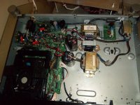
It does look a bit rough doesn't it but hey, it worked first time.
I can sort the wiring when the traff arrives...
I can sort the wiring when the traff arrives...
Fascinating thread. thanks so much for documenting it all so well. I'm about to buy a CD48 and carry out all the mods on the strength of it!
One question. On one of the early pics I can see the outputs connected to what looks like a Lampizator. Is it essential? And even if not, would you recommend one?
One question. On one of the early pics I can see the outputs connected to what looks like a Lampizator. Is it essential? And even if not, would you recommend one?
There I was thinking that everyone was yawning with boredom !
Thank you very much - really pleased that I've inspired someone to have a go.
The valve buffer in the pic is based on 6N6P's and was built merely to balance the impedance between my CD, passive volume control and the rest of the system - at least that's my understanding of it.
The most scary thing I made so far and you do not need one tbh.
I would NOT make another - you may be an Engineer however but I just play the Piano and solder things.. hahaha
It also depends what you are using downline of your CD player too I suppose.
I have a passive volume control so the buffer helps out there.
The voltage straight off the dac chip is such that volume settings were the same even after I removed the awful dual op amp and the output stage components.
It is a nice player in stock form and does exactly what Mr Fikus of the Lampizator site says....mid range and hf are very good and bass is borderline acceptable.
The biggest surprise of all was taking the signal off the dac chip to the coupling caps and then to the rca sockets.
It was a ' bloody hell 😱 ' moment which ended up with a big grin and me playing disc after disc for confirmation.
The next jump was the Oscons around the dac and changing the main ps caps at the back near the 5v regulator - the bass improves markedly at this point.
As always though the power supply is key and the tiny tx that powers the whole thing falls way short.
Since I've added additional power and regulators I've gained in every conceivable area and it now sounds lush, rich, detailed and powerful - like a much more expensive machine.
Just one warning - the board and it's pads are woeful and I've learned to do it cool and fast ( de soldering temps and time )
I use a quality Antex soldering station but it took me an age to get it right ( and destroyed two boards )
Pete's experience is similar to mine so take it easy if you can !!
You've read the thread and seen him stepping in occasionally too.
He's far more knowledgeable electronically and has been a bit of a god send - his list of bits will be useful to you too.
There are helpful people on this site - it's why I like it.
I've not finished it and the thread will grow a bit yet so get cracking right away and keep in touch.
It'll be great to see and hear your progress
Good luck
Andrew
Well, I've just bought one! I'll start collecting all the parts I need, ready for its arrival.
It sounds like I have a similar setup to yours, with a passive volume control, so I'm tempted to Lampetize the setup.
You would seem to be a musician who likes to dabble in engineering. I'm an engineer who likes to dabble in music! I do play the piano and organ and years ago I played the bassoon in several orchestras but no longer have either the time or the inclination for the bassoon. I do tend to choose my audio equipment from a musical perspective though - and that usually ends up needing lots of power and large, very accurate speakers!
You don't perchance have a list handy of all the parts you've used on your CD48 do you?
Well, I've just bought one! I'll start collecting all the parts I need, ready for its arrival.
It sounds like I have a similar setup to yours, with a passive volume control, so I'm tempted to Lampetize the setup.
You would seem to be a musician who likes to dabble in engineering. I'm an engineer who likes to dabble in music! I do play the piano and organ and years ago I played the bassoon in several orchestras but no longer have either the time or the inclination for the bassoon. I do tend to choose my audio equipment from a musical perspective though - and that usually ends up needing lots of power and large, very accurate speakers!
You don't perchance have a list handy of all the parts you've used on your CD48 do you?
Ahhh....at last someone with ears !!! hahahaha
I don't have a list but I could do one I suppose.
Having said that....it's all in the thread I think.....but :
Oscons x 4 ( 47uf x 16v ) biggest ps caps you can squeeze in without breaking anything ( 10,000 uf 25v ) Ultrafast soft recovery diodes x 4 ( 11dq10 ) erm....buy a cheap 5v regulator from tekdevice for main regulator ( at the back of the board - link in the thread )
and then you can get a few transformers of 9 volts and some more regulators ( 3 ) for dac chip. Oh yes....10uf coupling caps for direct dac out ( from pins 4 and 7 ) and some better rca sockets.
Filtered IEC inlet too.
In fact the order should be Oscons, ps caps and direct dac to coupling caps and rca's first. 2 hours...tops
Once you get over the shock of the sound start buying the other stuff....hahaha
It'll blow your socks off....assuming you don't fry the cr.. out of the board.
Like I said - practice on something with chosen solder at lowest temp you can get away with...and do it fast.
I use a pump/sucker to remove the bulk, you may use a wick ?
Don't pull too hard when removing bits.....honestly it's a real pig of a board if you rush....like I did :-(
Good luck
In fact I've got most of the bits spare you'll need to get started if you are interested :
Main ps caps ( new unused )
Diodes ( new unused )
Oscons ( new unused )
Coupling caps ( new unused )
RCA sockets ( in packaging )
Plus a 5 volt regulator I made using an LM317, 2 resistors and a tantalum cap which is miles better than the 7805 that's in.
I can photograph it all if you'd like to see them first - it's your call
Sounds like a useful start, for sure. Thanks for the information.
I'm tempted by the Tentlabs shunt regulators. Any comments or experience of them?
I'm tempted by the Tentlabs shunt regulators. Any comments or experience of them?
Sounds like a useful start, for sure. Thanks for the information.
I'm tempted by the Tentlabs shunt regulators. Any comments or experience of them?
I've never used one myself but they have a very good reputation. I'm not sure what their current rating is though, may be worth checking the current requirement of whatever you plan to use it for. It should be fine for powering the TDA1549 chip directly. May be more tricky if you're using it for all the 5v lines.
Pete
The 5v version has a rating of 80ma. I'm thinking of using 2 or 3 so they should be ok.
I'll be using something else for the display etc.
I'll be using something else for the display etc.
I've no experience of them either but 80ma is fine if you are using 3 - it'll be no problem.
Certainly small enough to squeeze them in at least.
The ones I used I'd had for a while anyway but were a bit of a bu....r to slot in.
The gains I made though will be similar for you too for sure.
Still waiting for a 100va 9v toroid to arrive...sigh🙁
Certainly small enough to squeeze them in at least.
The ones I used I'd had for a while anyway but were a bit of a bu....r to slot in.
The gains I made though will be similar for you too for sure.
Still waiting for a 100va 9v toroid to arrive...sigh🙁
I can't decide whether to use 2 or 3 x 50va toroidals with 2x6v windings each. That should give around 8.4v dc. The regs recommend between 7 and 11 volts input. That will give me up to 6 x 5v supplys plus the original transformer. 3 for the DAC chip, one for the audio, one for the other 5v requirements. Are 3 toroids overkill? Or should I stick to 2?
Hi,
3 for the dac chip might be overkill, try it with one feeding the 3 inputs as well and see if you notice any difference, you're probably getting into micro improvements at this stage. If you don't hear any difference you've saved some money.
One for the audio - you mean the opamp? That needs +/- 12v.
3 toroids will add some physical weight to the player if nothing else. I kept the original tx for the display ac, added 1 small one (7va) for the dac and a bigger one for everything else. If you do that remember you need at least +/- 12v available for the opamp (and possibly the mech).
Regards
Pete
Thnking about it, if I'm taking the output straight from the DAC, I'll be bypassing the op amp and thus won't need a 12v supply for that. I'm fairly sure the transport will need 12v though.I have a few 6+6v toroids tucked away. I'll wait and see what else needs what when the player actually arrives.
I did what Pete suggested - one tx and regulator for the three elements of the dac chip - there was a difference....hahaha.
Now with albeit 2 poor traffs and 3 regulators there's a massive difference. I'm going for 3 too once the clock is in - can't have too much VA from past experience imho.
I'm now fairly confident which bits to remove to add a clock too and when that arrives and goes in I'll post some details of ' how to '
I'd like to power the display too but am unsure of how to implement it. Need to read the service manual again and read Pete's post and pics
Do you have the service manual - I can send it if needed ?
Parcel in the post tomorrow morning btw ! e
- Home
- Source & Line
- Digital Source
- TDA1549 - Marantz CD48