at the moment i run tests, with 2*TDA1543, stacked, data for one inverted with 74HCT04, no regs, only original germanium bench power supply. I/V with Rs, Rref 82R, Rv 220R. Need to look if it really inverts.
Germanium ??? Ad162 ???
I don´t really know, "brand" is Leihgabe der Deutschen Forschungsgesellschaft 😉 and Forschung is what i use it for. Its from about 1962 and gives me up 30V 3A.
Sound i don´t comment on yet. If i tell you all its " the best i ever heard" noone will help me building a balanced AD1865N-K Dac.
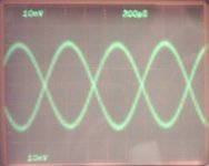
At the moment i play sinewaves and listen them throug a TEK7904....
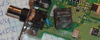
Hey, its a ugly piece of veroboard prototype.
signal 2 channels 1:10probe:
Attachments
lower verobard (holes and stripes) connector for I2S, socket for DAC, decoupling, one Rref, passive I/V for + DAC, Dacs soldered together under upper verobrad, upper veroboard with 74HCT04, inverters decoupling, Rref, passive IV for - DAC
400mV swing is not much, 3 or 4 times this would be better
400mV swing is not much, 3 or 4 times this would be better
Attachments
till said:The proble is see isn not any offset, all the I/V stages ( resistor and Pass) are capacitive coupled. I also doubt the D1 stage has problems with the 2mA offset, but this would be no prob to solve.
What i want to know: is simply inverting instead of true inverting a word with real 16Bit infomrmation, or is there information lost?
In case its a real 16Bits word, why do we need anything more than one inverter / phase splitter?
For a DAC using one DAC for L+- and one for R+- we need an I2S mode thats left justified and a DAC accepting separate DL and DR, so its easy to feed it.
The offset is not a problem at the output of an i/v stage (where the cap is you mention), it could be a problem for the working of the stage itself. You start asking for 2mA from the i/v circuit by the DAC (a TDA1541 that is). D1 i/v circuit expects no current at silence (PCM63 with current pin connected).
No information is lost at inverting, you just create an offset of 1 lsb at dig silence.
The I2S mode does not change for L+- and R+-. In my case it's the same I2S signal (with 32bit words), just the information in the words is changed: L/R becomes L/-L and R/-R.
The only advantage for doing this is that you use one DAC per channel (which than can have a different PS etc.).
Greetings,
Should be: No information is lost at inverting, you just create an offset of 1 lsb.
But for your 1865, guess you have never seen this ??😀 😀 😀
Since the 8414 can only output two's complement, the AD seems to use that format. So inverting to get -L/-R is a matter of swapping using two more of the '04 inverters after the '08.
Found this on the net a while ago, don't know anything about it!
Hope i made up for last night's mistake 😀
😀
But for your 1865, guess you have never seen this ??😀 😀 😀
Since the 8414 can only output two's complement, the AD seems to use that format. So inverting to get -L/-R is a matter of swapping using two more of the '04 inverters after the '08.
Found this on the net a while ago, don't know anything about it!
Hope i made up for last night's mistake
😀Attachments
Oh no, chat mode again.
But anyhow, i'm off to bed now. This is not good for my health and i'm not staying up for the F1.
As you can see from the link to AA by Elso, it got it right the first time.... Yesterday was more a case of bad memory and not finding/looking at the document before reacting. Getting older
I'm off,
But anyhow, i'm off to bed now. This is not good for my health and i'm not staying up for the F1.
As you can see from the link to AA by Elso, it got it right the first time.... Yesterday was more a case of bad memory and not finding/looking at the document before reacting. Getting older
I'm off,
till said:some critics on the resistor values?
What is the point of inverting WS ?
wrong cut & paste, of corse data is inverted. I did cut the DAC from circuit in #19 and did not correct it before. Stupid mistake.
What i don´t understand is my resistor values i found by trial and error / listening.
Much lower than in all the circuits around with TDA1543. But it did not play with the high values, only very silent and lots of noise with higher values.
What i don´t understand is my resistor values i found by trial and error / listening.
Much lower than in all the circuits around with TDA1543. But it did not play with the high values, only very silent and lots of noise with higher values.
AOR and AOL are connected on the second DAC, I hope it's mistake on the schematic. If not, I think I know where your problem comes from 😉
of corse its a mistake, you know the summ of all mistakes is constant - at least if you post circuit diagrams in the middle of the night.
to keep all of you awake (joke) i make at least one mistake in each circuit posted - in #154 the connection of R- and L-, in #146 additional inverter in wrong line.
What is a big ??? are those resistor values. With those resistor values commonly seen around for passive I/V i have no good result. Very silent and noise. At 5V i have good results with 82R / 220R at 7,5V 1k / 680R.
I´m not really happy with passive I/V as i have not much voltage gain in my system (BZLS and ZEN 4) and voltage output of the passive I/V stage is not much. With higher resistors Voltage does not get more but less and noise. I have to look at D1 stage and order parts.
Why does the 74HCT04 gets warm?
Why the heck TDA1541 are that expensive at Reichelt? (next step)
For the AD1865: what about making left justified from right justified by making a new Wordclock. A counter startet with transint of normal Wordclock, and counting 19Bitclcoks now, than making a transient for new Wordclock.
My impression is with the AD left right splitting will be easyer, i have more of them on hand than 1541, and i hope it will be better.
Any one idea for JST connectors for I2S connector of CD PRO2 ?
http://www.daisy-laser.nl/homeoptics/page29.html

- Status
- Not open for further replies.
- Home
- Source & Line
- Digital Source
- TDA1541A/S1 Arrangements