Nope,
I AM STUPID.
Just found the BB application note (have a hardcopy) again...
And i found this, after i could not understand myself anymore.. Wrote this (i'm R2D2 there) long time ago on AA (elso's link posted here):
Still the inverse of a two's complement number is "all bits inverted (done with the '04) + 1. Your LSB is NOT correct anymore.
Example with 4 bits: 5 = 0101, -5 is then 1010 (your inverter) + 1 = 1011 !
So you and Bernard were right about incrementing. My bad.
So my plan to 'find the lsb in the frame' is useless, since incrementing means other bits change too. So a small DSP is required, i guess.
Should have gone to bed long time ago...
Another thing to correct: I2S is specified as two's complement.
GuidoB
There is another problem IMHO
Again for simplicity a four bit word.
15 = 1111
-15 = 10001
We cut the first 1 and get 0001 which is 1 for the TDA.
That would not be good if 0 = 0mA and 15 = -4mA.
Ok, it's too late for today need to sleep...
Again for simplicity a four bit word.
15 = 1111
-15 = 10001
We cut the first 1 and get 0001 which is 1 for the TDA.
That would not be good if 0 = 0mA and 15 = -4mA.
Ok, it's too late for today need to sleep...
Bernhard, as the words are twos complement and the range of Iout is 0 to -4mA it must be like
1000000000000001 = 0mA = min (~ -32767)
and
0111111111111111 = -4ma = max (~ +32767)
0000000000000000 = -2mA = 0
The TDA doe not need to know that it is negativ, he only needs to be feed with symmetrical words. Onwe channel with the sample and the other with the inverse. The original sample may be positive or negative by itself depending if it is from the + or - halfwave of waveform.
guido, i´m glad this is sorted out. So we need a descision in the next days if we find a simple and new solution or have to look for some Processor.
edit:
Bernhard : for #122, B'1111' in twos complement is never 15. but it is -1. sleep well
From the appl note.
For bit exaples with Vout. BTC coding scheme:
-full scale coded 1000 V=-5.000
-full scale + 1 lsb coded 1001 V=-4.375
-0.5 fs coded 1100 V=-2.500
-1LSB coded 1111 V=-0.625
0 coded 0000 V=0.000
+1LSB coded 0001 V=0.625
+0.5 fs coded 0100 V=2.5
full scale coded 0111 V=4.375
So inverting full scale brings 1000+1=1001.
That is one lsb next to -full scale, V=-4.375
Inverting -full scale (1000) brings 0111+1=1000
So the rule invert and increment +1 is fine, except if the
data going in is -full scale. Guess that happens not so often😉
The number of options is even we can make with binary coding
is even (2^x is always even) So if one option is 0 than there cannot be equal options for plus and for minus. There are more
options is a signal is negative. -FS = -5, +FS = +4.375.
For a tda1541 i guess:
100000000000000 = -4mA -FS
000000000000000 = -2mA 0
011111111111111 = 0mA +FS
I'm off to bed, getting really
nverting -full scale (1000) brings 0111+1=1000 So the rule invert and increment +1 is fine, except if the
data going in is -full scale. Guess that happens not so often
There is no positive value with abs(-full scale). This means a symmetrtical waveform reaching - full scale would digitally clip at the positive half of waveform. in case this happens a (- full scale) on one side of the balanced DAC is not the worst thing to happen... In case we use a DSP and are pedantic we could filter all - full scale samples and set them to (- full scale) +1
A MSP430 looks like beeing able to handle the work and is easyer to work with than real DSPs. Samples are free and programmer not too expensive.
till said:
There is no positive value with abs(-full scale). This means a symmetrtical waveform reaching - full scale would digitally clip at the positive half of waveform. in case this happens a (- full scale) on one side of the balanced DAC is not the worst thing to happen... In case we use a DSP and are pedantic we could filter all - full scale samples and set them to (- full scale) +1
A MSP430 looks like beeing able to handle the work and is easyer to work with than real DSPs. Samples are free and programmer not too expensive.
Had some thoughts after last nights "session". So how bad is it? We are one lsb off all the way:
-8 1000 -> 0111 = +7
-7 1001 -> 0110 = +6
-6 1010 -> 0101 = +5
-5 1011 -> 0100 = +4
-4 1100 -> 0011 = +3
-3 1101 -> 0010 = +2
-2 1110 -> 0001 = +1
-1 1111 -> 0000 = 0
0 0000 -> 1111 = -1
+1 0001 -> 1110 = -2
+2 0010 -> 1101 = -3
+3 0011 -> 1100 = -4
+4 0100 -> 1011 = -5
+5 0101 -> 1010 = -6
+6 0110 -> 1001 = -7
+7 0111 -> 1000 = -8
So the neg signal is like the positive with 1 lsb 'offset'. A 'dc' component on the waveform. Not to much to worry about, the 1541 already has -2mA offset already. Does not really matter if its a few nA more.
New statement:
Is is better just to invert and be 1 lsb off than to follow the rule
and go wrong with -FS.
One negative thing i can think of is that a dac would be made to be most linear at 0. Now zero is at -1lsb which could be less accurate. 😕
Good luck with your dsp!
Greetings,
If the LSB error only gives an offset, you have 2 solutions
-have caps at the I/V's output, or at the amp's input
-live with it. After all, on a 2Vrms output, it's only 43µV
And as Elso said on another topic, Philips used this configuration on the CD-850
-have caps at the I/V's output, or at the amp's input
-live with it. After all, on a 2Vrms output, it's only 43µV
And as Elso said on another topic, Philips used this configuration on the CD-850
Bricolo said:If the LSB error only gives an offset, you have 2 solutions
-have caps at the I/V's output, or at the amp's input
-live with it. After all, on a 2Vrms output, it's only 43µV
And as Jean-Paul or Elso said on another topic, Philips used this configuration on the CD-850
The offset is already -2mA before the i/v. So you need to
compensate for this before the i/v or build a i/v circuit that can handle this. As discussed earlier (pass D1 / PCM63 / pedja's dac) here.
The 850 uses bitstream dac's. Better example is the
marantz cd7: two tda1541 S2's in diff mode. Two big dsp's to feed the data, but those are also for oversampling.
Gr,
I think that the CD850 is closer to what you want to do.
Easy to do, uses logic and not a dsp...
Easy to do, uses logic and not a dsp...
inded DSP is a lot of work. A MC with DSP features should be much more easy, if someone is allready skilled how to use it.
The proble is see isn not any offset, all the I/V stages ( resistor and Pass) are capacitive coupled. I also doubt the D1 stage has problems with the 2mA offset, but this would be no prob to solve.
What i want to know: is simply inverting instead of true inverting a word with real 16Bit infomrmation, or is there information lost?
In case its a real 16Bits word, why do we need anything more than one inverter / phase splitter?
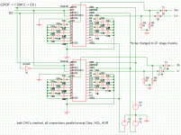
The 2 DACs only need to connected to PS is same way, what about stacking them and only separately connect the pins necessary?
In this case i can´t see need for logic chips. PALs etc, and #40 should simply work.
For a DAC using one DAC for L+- and one for R+- we need an I2S mode thats left justified and a DAC accepting separate DL and DR, so its easy to feed it.
If using the AD1865 and supressing all clock signals after 19th clock and allow **** again with Fsync transient for again 19 clocks, + inverting the dataline for DL´s , and invering one of the (LL/LR)s it should work.
The proble is see isn not any offset, all the I/V stages ( resistor and Pass) are capacitive coupled. I also doubt the D1 stage has problems with the 2mA offset, but this would be no prob to solve.
What i want to know: is simply inverting instead of true inverting a word with real 16Bit infomrmation, or is there information lost?
In case its a real 16Bits word, why do we need anything more than one inverter / phase splitter?
The 2 DACs only need to connected to PS is same way, what about stacking them and only separately connect the pins necessary?
In this case i can´t see need for logic chips. PALs etc, and #40 should simply work.
For a DAC using one DAC for L+- and one for R+- we need an I2S mode thats left justified and a DAC accepting separate DL and DR, so its easy to feed it.
If using the AD1865 and supressing all clock signals after 19th clock and allow **** again with Fsync transient for again 19 clocks, + inverting the dataline for DL´s , and invering one of the (LL/LR)s it should work.
I know it know 😀
We need it if we want to load data in both channels of a TDA chip simultanously.
We need it if we want to load data in both channels of a TDA chip simultanously.
sound good, I hope this is also a step towards connecting AD1865
http://www.intersil.com/data/an/an9657.pdf
http://www.intersil.com/data/an/an9657.pdf
At the moment i test the interconnect CD PRO2 I2S to DAC, and with TDA1543 i get nothing with Vref to GND = 1k and RI = 1k. Some music with Vref to GND = 56R and RI= 220R
ok, first we learn from practical experience: do not run the TDA1543 DAC with more than 5V, beacause the 74HCT04 becomes >really< hot if you try this.
- Status
- Not open for further replies.
- Home
- Source & Line
- Digital Source
- TDA1541A/S1 Arrangements