I am a little confused about MSB and LSB.
The LSB is the one that makes the smallest change and MSB makes the biggest change ?
Here was written MSB does not have to be inverted.
What I got:
444 = 0110111100
-444= 1001000100
The three least significant bits are equal.
There are no rules, sometimes 1, sometimes 2, sometimes three LSBs are equal.
What am I missing here ?
444. in 16 bit word, Zweierkomplementdarstellung
444. = B'0000000110111100'
invert -> 1111111001000011
incr -> 1111111001000100 = -444.
siehe #76 und #52 or google zweierkomplementdarstellung
444. = B'0000000110111100'
invert -> 1111111001000011
incr -> 1111111001000100 = -444.
siehe #76 und #52 or google zweierkomplementdarstellung
till said:444. in 16 bit word, Zweierkomplementdarstellung
444. = B'0000000110111100'
invert -> 1111111001000011
incr -> 1111111001000100 = -444.
siehe #76 und #52 or google zweierkomplementdarstellung
I don't question this.
But here was written, that instead of inverting the whole word plus adding 1, it is possible to just invert the whole word except for the MSB.
???
Ah! we have to discriminate between LSB and MSB of our 16 Bit dataword, and of the word - row of bits coming out of the CS8412 or I2S in one wordclock cycle. When is written the MSB (the first one in the hole bunch of bits in one frame) does not have to be inverted, its the Bit that is not part of the dataword, as the 2nd bit in the frame is the MSB of our dataword. After we separated the dataword from the other bits in one frame its the invert and increment.
except the LSB?
from #34:
I don´t really understand why inverting all but the LSB would be correct twos complement inverting.
maybe twos complement is not = twos complement?
but datasheet says:With OB/TWC connected to VDD the mode is the same but data format must be in two’s complement. And guido in #33 OB/TWC to Vdd is I2S mode.
This tells us words are in twos complement and twos complement is inverted as above.
from #34:
As Ray pointed out: inverting the dataline is not a 100% inversion of the signal. The correct procedure would be : invert bit 2 to 16, but do not invert bit 1 (LSB). So by inverting the dataline, you're one bit off.
I don´t really understand why inverting all but the LSB would be correct twos complement inverting.
maybe twos complement is not = twos complement?
but datasheet says:With OB/TWC connected to VDD the mode is the same but data format must be in two’s complement. And guido in #33 OB/TWC to Vdd is I2S mode.
This tells us words are in twos complement and twos complement is inverted as above.
till said:
Ah!
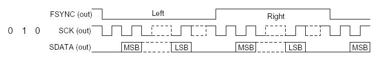
So SCK and FSYNC are active low signals and the word starts after one clock cycle of the SCK signal after FSYNC goes low.
What is in the data line during our wait cycle ? Garbage ?
As Ray pointed out: inverting the dataline is not a 100% inversion of the signal. The correct procedure would be : invert bit 2 to 16, but do not invert bit 1 (LSB). So by inverting the dataline, you're one bit off.
Hä ?
Bit 2 to 16 of the data word ?
Otherwise it should be bit 2 to 17.
Otherwise one bit would be missing on the end.
???
Fsynk is WS and its low for the left channel word and goes high one bit before the MSB of the righ channel word starts. Then it goes low again one bit before the next leftchannel word starts. There are more than 16 bit transmitted in each frame the WSis high (low). There are as posted somewere before 32 bit transmitted, but the number is not of interest for us. We only need the 2nd to the 17th as this are, MSB first, our 16Bit containing the sample. The others are garbage.
As i understand until now.
i can only say hä? too, i did not understand what inverting all but LSB means here.
As i understand until now.
i can only say hä? too, i did not understand what inverting all but LSB means here.
till said:Fsynk is WS and its low for the left channel word and goes high one bit before the MSB of the righ channel word starts. Then it goes low again one bit before the next leftchannel word starts. There are more than 16 bit transmitted in each frame the WSis high (low). There are as posted somewere before 32 bit transmitted, but the number is not of interest for us. We only need the 2nd to the 17th as this are, MSB first, our 16Bit containing the sample. The others are garbage.
As i understand until now.
Okay, FSYNC low left, high right.
But
"invert bit 2 to 16"
does definitely say that only 15 bits have to be inverted.
Does not make any sense to me.
Arbeitshypothese
we invert all and increment, as this should be correct. If not someone will post and correct us.
we invert all and increment, as this should be correct. If not someone will post and correct us.
Here we go:
Check out pedja's AD844 design, it has a +2mA current source to do this.
MSB was type error, i meant LSB! Seems to have caused a lot of confusion...
Serial I2S does NOT have to be 16bit words, with 8412 and 7220 it's 32bit words. I2S does not tell you the coding of the data, could be anything. Check out the 1541 datasheet. Both serial modes are I2S, where one is offset binary and one two's
complement (the one we use).
TDA1543 != TDA1543A: first is two's complement, second is Sony Japanese. You will not find a datasheet for the last one...
For Elso: trying to get the dac's as equal as possible by using them +R/-R +L/-L and using S1 matched version.
Back to correcting the LSB, i'll try to explain. If you feed my design with 16 bit words it is very easy: We have WS toggling at LSB. Thank god for that!! Delay with one ff as i have done and you know where the data is. Now XOR WS and WSdelayed and you have this:
MSBXXXXXXXXXXXXXLSBMSB data
1111111111111111000000 WS
1111111111111111111000 WS delay
0000000000000000111000 WS XOR WSdelay
So you have a 'marker' for the LSB. That can be used to not invert data if this is high. Since the data is 16 bit now, the shift register needs to be two times 16 bit. So the connections to the 4517 should not be 32 and 64 output, but 16 and 32. Minor cut and
a small wire.
I will have a look at some receivers to see if i can find one that works with 16bit words i2s out. If it exists, i will use it and correct the LSB error.
And again, a nice programmable cpld can do this easly with 32bit words...
Find yourselfs the application bulletin "Coding schemes used with data converters" from BB.
Greetings,
guido said:Here we go:
Check out pedja's AD844 design, it has a +2mA current source to do this.
MSB was type error, i meant LSB! Seems to have caused a lot of confusion...
Serial I2S does NOT have to be 16bit words, with 8412 and 7220 it's 32bit words. I2S does not tell you the coding of the data, could be anything. Check out the 1541 datasheet. Both serial modes are I2S, where one is offset binary and one two's
complement (the one we use).
TDA1543 != TDA1543A: first is two's complement, second is Sony Japanese. You will not find a datasheet for the last one...
For Elso: trying to get the dac's as equal as possible by using them +R/-R +L/-L and using S1 matched version.
Back to correcting the LSB, i'll try to explain. If you feed my design with 16 bit words it is very easy: We have WS toggling at LSB. Thank god for that!! Delay with one ff as i have done and you know where the data is. Now XOR WS and WSdelayed and you have this:
MSBXXXXXXXXXXXXXLSBMSB data
1111111111111111000000 WS
1111111111111111111000 WS delay
0000000000000000111000 WS XOR WSdelay
So you have a 'marker' for the LSB. That can be used to not invert data if this is high. Since the data is 16 bit now, the shift register needs to be two times 16 bit. So the connections to the 4517 should not be 32 and 64 output, but 16 and 32. Minor cut and
a small wire.
I will have a look at some receivers to see if i can find one that works with 16bit words i2s out. If it exists, i will use it and correct the LSB error.
And again, a nice programmable cpld can do this easly with 32bit words...
Find yourselfs the application bulletin "Coding schemes used with data converters" from BB.
Greetings,
This is very difficult to understand without seeing the design.
But still:
Why shall only 15 bits be inverted ?
guido said:copy/paste the timing diagram into notepad.
makes more sence then....😉
Which timing diagram ?
- Status
- Not open for further replies.
- Home
- Source & Line
- Digital Source
- TDA1541A/S1 Arrangements