tc6wd (used in the arrays - cheap one) vs tc6fc00 (neo expensive one, my fave of the tc6)
One thing that worries me, valid or not, is the incredibly shrouded frame these drivers have on the back. Like I said, no idea if it's valid or not but I worry that seemingly closed back has a detrimental effect on the potential of those drivers. The TC9 FD18-08 is very open in comparison.
This is just an observation based on the pictures I've seen. As good results have been had with closed back mids on Synergy/Unity type speakers I don't know how valid that observation is.
I do hope you're willing to check the WD in the FC enclosure, just to be sure of the results you have posted.
I'll check them in the same enclosure just for curiosity's sake, but I know that dip isn't in the driver ( from the raw measurements of the arrays. )
As for the rear venting, its totally adequate for the limited amount of air these drivers are moving. Performance is not akin to a sealed driver at all. Care must be taken with the mounting so that the vents aren't blocked though.
I'll take a picture when I redo the measurements.
As for the rear venting, its totally adequate for the limited amount of air these drivers are moving. Performance is not akin to a sealed driver at all. Care must be taken with the mounting so that the vents aren't blocked though.
I'll take a picture when I redo the measurements.
The limitation with The Edge is that it assumes all drivers are completely rigid radiators, which isn't the case for real drivers unless they are operating below their cone breakup node (below a couple kHz). I think it also assumes they are planar instead of conical. The implication is that the off-axis response of a driver compared to on-axis response in The Edge is not quite the same as real life. It also doesn't consider the 'cavity effect' which is edge diffraction due to the cone cavities of other drivers. Despite this it is still very useful for comparing different driver layouts on a baffle.
In real life you'd have to make sure your measurements aren't influenced by room effects. This probably means hoisting the array meters up in the air in a large open space and gating your frequency response measurement appropriately. If you measure in a room then the measurements can only be accurately compared above the gating frequency and you have to be dead certain that the position of the speakers and mic are exactly the same in both cases.
Very good points on using a simulation program. The differences within even the same driver size play a role - straight-sided vs. curvilinear cones, motor inductance, cone mass, etc.
Very good points on using a simulation program. The differences within even the same driver size play a role - straight-sided vs. curvilinear cones, motor inductance, cone mass, etc.
Yes, and I think TMM really hit the nail on the head here:
TMM said:I think it also assumes they are planar instead of conical
That explains why the driver size (in the Edge) doesn't affect the response in the ways theory predicts. The Edge seems good at, well, simulating baffle edges. The driver models are extremely simple. From Tolvan's website:
"The rectangular shape can also be used to approximate an array of equally spaced loudspeakers."
"It does not, however include cone break-ups, since all of the sources are of equal magnitude and phase"
(Home of the Edge)
So, I don't think we should be taking simulations from the Edge very seriously, except as they relate to baffle diffraction.
Thanks for the tip on the latest Keele Paper. Very accessible paper like his other ones on CBT. I found this paper disappointing in its lack of content. Weesayso will not get his CBT Step Response even from the7th(?) paper by the inventor of the CBT.
Yes, I agree that it's a short paper for Don! 😀
Based on his engineering experience as well as having reviewed many speakers
he tends to focus on other design issues that he feels are more important than time behavior.
Here's a 70" tall array (6.5" 2-way) that has shading. Measurements taken at the center of the array from 1,2,3, and 4M.
http://www.audiocircle.com/image.php?id=140418
http://www.audiocircle.com/image.php?id=140418
Last edited:
3.5" v 6" driver array comparison
TMM, here is some contradicting evidence.
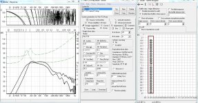
Here are some plots that compare a TC9 array versus a Jamo 6" woofer array. I have both these drivres (and in fact I have the TC9 array itself). This is BASTA, which is Edge's big brother. Top line in all figures is the TC9.
Clearly, the 6" array comb filtering starts approximately an octave lower. The second picture shows a closeup. Now, the driver density value in Basta/Edge has a big impact on the response smoothing. See the third picture, where driver source density has been reduced to one for both systems. What are we to believe?
In a real array, if we assume larger drivers, then the acoustic centers will be farther apart, and therefore, phase shifts that produce peaks and dips will start at a lower frequency. Pretty simple really. This has nothing to do with driver directionality, which I believe all models are ignoring -- our theoretical model and the simulators. But the conclusion is still the same: frequency at which comb filtering starts has nothing to do with the height of the array.
I don't know what is the difference between the Edge and Basta, both are developed by the same guy, but clearly, our sims are producing different results.
TMM, here is some contradicting evidence.
Here are some plots that compare a TC9 array versus a Jamo 6" woofer array. I have both these drivres (and in fact I have the TC9 array itself). This is BASTA, which is Edge's big brother. Top line in all figures is the TC9.
Clearly, the 6" array comb filtering starts approximately an octave lower. The second picture shows a closeup. Now, the driver density value in Basta/Edge has a big impact on the response smoothing. See the third picture, where driver source density has been reduced to one for both systems. What are we to believe?
In a real array, if we assume larger drivers, then the acoustic centers will be farther apart, and therefore, phase shifts that produce peaks and dips will start at a lower frequency. Pretty simple really. This has nothing to do with driver directionality, which I believe all models are ignoring -- our theoretical model and the simulators. But the conclusion is still the same: frequency at which comb filtering starts has nothing to do with the height of the array.
I don't know what is the difference between the Edge and Basta, both are developed by the same guy, but clearly, our sims are producing different results.
Attachments

Last edited:
Anyway, TMM, I think we've made our points. Why not let dynomike progress with his build? We can talk in my thread if you'd like. I think there is some real promise here and even the possibility of measured data from another array build!!
Anyway, TMM, I think we've made our points. Why not let dynomike progress with his build? We can talk in my thread if you'd like. I think there is some real promise here and even the possibility of measured data from another array build!!
Your simulation looks closer to what I've measured in various arrays.
Now, the driver density value in Basta/Edge has a big impact on the response smoothing. See the third picture, where driver source density has been reduced to one for both systems. What are we to believe?
The graph where source density=1 is more believable in terms of modelling an array of circular drivers..
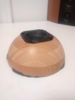
More measurements of the TC6 variants coming up. The test enclosure is a hemispherical IKEA bowl which will sit atop a pile of blankets, so the results should be pretty close to infinite baffle. A pair of these bowls makes a very nice sounding TC6 enclosure actually...
Also attached picture of the driver venting (for wesayso)
Attachments

Keele paper
AES Library is where I had to go....$20....#9387.
I'll look a bit harder for it, I didn't see it on the busy site from Don. Maybe I just missed it, not hard to get lost there 🙂.
Or is it only available in the AES library?
AES Library is where I had to go....$20....#9387.
Subjectivity in the end is the guiding acoustic principle in all designs.......it's the singular reason we have so many principally different alignments occupying home Hifi for decades. Each alignment of system will exhibit traits that are pleasing to some and disappointing to others. I too have shared the OPs experience with full range arrays and have experienced multi way arrays where instruments we expect to radiate from a small single point in space are now grossly exaggerated on size. There's also the extreme mismatch in vertical vs horizontal directivity.
But for some, these are all fair tradeoffs against a very dynamic and low distortion system. To each their own of course and I summize that mantra will continue within Hifi until the dawn of time. Line arrays, CD devices, Unity/Synergy, Coincident drivers, Dipole,..........each very different on some fronts and all equally viable and enjoyed by many. I've come to realize that the full range array isn't suitable for my space or listening flavor. It's been an eye opener even further after reviewing Wesayso's thread and this one. My former and after WMTMW and similar variants were more enjoyable in almost every subjective aspect and the more dynamic the system, the better........which attributed for me what I DID enjoy about the fullrange array........and the point source imaging of stringed instruments vs the 7ft tall violin..........the things I found unnatural.
But for some, these are all fair tradeoffs against a very dynamic and low distortion system. To each their own of course and I summize that mantra will continue within Hifi until the dawn of time. Line arrays, CD devices, Unity/Synergy, Coincident drivers, Dipole,..........each very different on some fronts and all equally viable and enjoyed by many. I've come to realize that the full range array isn't suitable for my space or listening flavor. It's been an eye opener even further after reviewing Wesayso's thread and this one. My former and after WMTMW and similar variants were more enjoyable in almost every subjective aspect and the more dynamic the system, the better........which attributed for me what I DID enjoy about the fullrange array........and the point source imaging of stringed instruments vs the 7ft tall violin..........the things I found unnatural.
TMM, here is some contradicting evidence.
Here are some plots that compare a TC9 array versus a Jamo 6" woofer array. I have both these drivres (and in fact I have the TC9 array itself). This is BASTA, which is Edge's big brother. Top line in all figures is the TC9.
Clearly, the 6" array comb filtering starts approximately an octave lower. The second picture shows a closeup. Now, the driver density value in Basta/Edge has a big impact on the response smoothing. See the third picture, where driver source density has been reduced to one for both systems. What are we to believe?
In a real array, if we assume larger drivers, then the acoustic centers will be farther apart, and therefore, phase shifts that produce peaks and dips will start at a lower frequency. Pretty simple really. This has nothing to do with driver directionality, which I believe all models are ignoring -- our theoretical model and the simulators. But the conclusion is still the same: frequency at which comb filtering starts has nothing to do with the height of the array.
I don't know what is the difference between the Edge and Basta, both are developed by the same guy, but clearly, our sims are producing different results.
I'd say Basta does the better job as I can relate this sim to my "reality". It shows how the smaller driver array having the smoother results.
AES Library is where I had to go....$20....#9387.
Thanks for that. As you've told me a bit about the content I think I'll skip it for now. I've read the intro but am most curious to see some graphs.
I too have shared the OPs experience with full range arrays and have experienced multi way arrays where instruments we expect to radiate from a small single point in space are now grossly exaggerated on size. There's also the extreme mismatch in vertical vs horizontal directivity.
I think the exaggerated height is an artifact of asymmetrical room treatment, as I noted in my OP. When the array has a different reverberent sound at different heights, the image is bound to be pulled in the direction that has the highest overall sound energy, and suffer from increased apparent source height.
I have not experienced ANY height artifacts since shortening my arrays to a level where the room has a similar amount of diffusing / absorbing objects from top to bottom. Dry close mics sound dry, close, and small. I would be most interested to try the arrays in a completely empty space to confirm this hypothesis.
In theory, line arrays should produce absolutely no height information, not even revealing the height of the listening position in the room, or the dimensions of the room itself (due to a lack of floor / ceiling bounce).
As for the mismatch in horizontal vs vertical directivity, this simply isn't a problem. We're in the nearfield in terms of vertical directivity, so the dispersion is functionally complete, filling the whole room. Horizontally - the speakers are tightly in the corners, so there aren't any discernible sidewall reflections. What I'm saying is that in practice, the (lack of) directivity is very well matched.
Last edited:
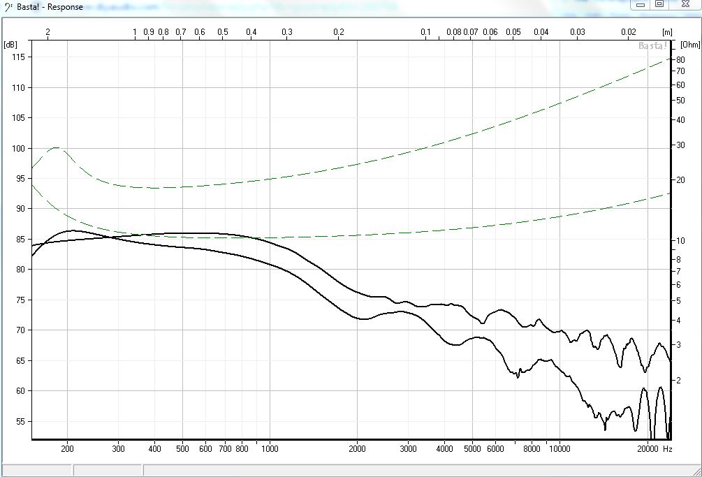
TC6WD mounted on IKEA bowl, open backed on top of a pile of cushions. (approximating infinite baffle)
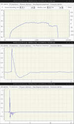
Measurements match up with the published specs pretty well.
This is the WD mounted in the other enclosure, right? It's still a big drop at high frequencies (~5500 Hz). The impulse is relatively clean on first look, but not as clean as it's neo sister driver.
Any chance I can persuade you to start using REW? 🙂 An early waterfall plot might show some info on the ringing after the main pulse. Like I said, we get the driver that is used back on steroids.
Yes, its the same enclosure I used for the neo driver. Its a crazy steep drop, but that's what the specs show as well. Not sure if this driver is better/worse than others. I ran out of good drivers at some point during the build - ordered 20% extra for QC but 10% were damaged in shipping, so I basically only have the worst of the bunch free for testing individually. This one had a dented dustcap but otherwise seems fine.
If cost were no object, I absolutely would have used the FC00 or FD00 (or perhaps the 02 to get lower midrange distortion, at the expense of smooth FR..)
Sure, I'll install REW on my Windows setup. Seems to be necessary to get the next level of information from measurements.
Of course, I agree the room and the speaker topology need to work together to achieve a good result however it's only useful data to yourself if measure a particular configuration in your room without gating out room effects.I realize you're talking about comparing two different arrays in the story above, but the suggested measurement method is damn near impossible for all of us. And we wouldn't have to do it like that, only if we want to compare two theoretical cases.
The suggested method is valid if you would want to produce a speaker with a universal correction. Most of us building these arrays do know we need EQ. We also have and use a room to host the speakers. Maybe even use nearby walls to our advantage. The OP certainly does. With frequency dependent windowing we can go a long way to correct the speaker at the listening position within that room. Of coarse we can't get rid of the room completely, even with FDW but with enough effort we can learn to "read" the room.
I never treated my speakers separately from the room. They work together to do what I want them to.
Measuring without gating and coming to the conclusion that configuration x works better than configuration y will have little value to me because my room has different dimensions to yours. In the context of arrays this point only becomes more important.
Measurements done in a large outside space with appropriate gating are replicable by everyone. There may also be some value in placing the speaker appropriately far away from walls and performing a gated measurement to observe the floor and ceiling effects without side wall effects. Of course, it would only be valid for people who have the exact same listening distance and floor to ceiling height.
FWIW a speaker that behaves poorly in anechoic conditions, will also behave (even more) poorly in a real room. That is the value in doing (quasi-)anechoic measurements and simulations. If we ignore theory and anechoic measurements then trying to make a speaker that performs well in a real room becomes dumb luck.
Last edited:
<ontopic>
The FC, FD and WD versions are all quite different beasts. The FC is the better one obviously.
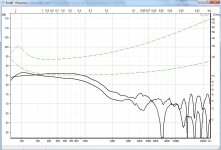
FC00-04 measured on my 0.9x1.2m test baffle:


FD00-04


I haven't used the WD version but according to the datasheet there is a ~10dB shelf from 4kHz up. It's clearly engineered to be used with a tweeter without a crossover or be able to use a very simple crossover, it's not really supposed to be a 'fullrange' imo. Unfortunately the roll off is too sharp to shape into a proper slope with only passive components but I can see how it is "good enough" where someone wants to use it with a cheap tweeter in a product (e.g. inbuilt speakers in a television) and get away with the absolute minimum amount of components.
One positive of the WD's huge shelf in the frequency response is that all of the non-linear distortion that lands above 4kHz should be reduced by about 10dB. Assuming the distortion caused by the motors of the FD and WD are the same, the WD should be significantly cleaner in the upper midrange and the lower treble.
Also consider this, the TC7FD00. It's a better driver than all of the TC6 variations imo


The FC, FD and WD versions are all quite different beasts. The FC is the better one obviously.
FC00-04 measured on my 0.9x1.2m test baffle:
FD00-04
I haven't used the WD version but according to the datasheet there is a ~10dB shelf from 4kHz up. It's clearly engineered to be used with a tweeter without a crossover or be able to use a very simple crossover, it's not really supposed to be a 'fullrange' imo. Unfortunately the roll off is too sharp to shape into a proper slope with only passive components but I can see how it is "good enough" where someone wants to use it with a cheap tweeter in a product (e.g. inbuilt speakers in a television) and get away with the absolute minimum amount of components.
One positive of the WD's huge shelf in the frequency response is that all of the non-linear distortion that lands above 4kHz should be reduced by about 10dB. Assuming the distortion caused by the motors of the FD and WD are the same, the WD should be significantly cleaner in the upper midrange and the lower treble.
Also consider this, the TC7FD00. It's a better driver than all of the TC6 variations imo
Last edited:
Of course, I agree the room and the speaker topology need to work together to achieve a good result however it's only useful data to yourself if measure a particular configuration in your room without gating out room effects.
Measuring without gating and coming to the conclusion that configuration x works better than configuration y will have little value to me because my room has different dimensions to yours. In the context of arrays this point only becomes more important.
Measurements done in a large outside space with appropriate gating are replicable by everyone. There may also be some value in placing the speaker appropriately far away from walls and performing a gated measurement to observe the floor and ceiling effects without side wall effects. Of course, it would only be valid for people who have the exact same listening distance and floor to ceiling height.
FWIW a speaker that behaves poorly in anechoic conditions, will also behave (even more) poorly in a real room. That is the value in doing (quasi-)anechoic measurements and simulations. If we ignore theory and anechoic measurements then trying to make a speaker that performs well in a real room becomes dumb luck.
While I agree with what you are saying here one must remember the type of speaker the OP is trying to tame. He chose to make a corner array and as such it's placement in the room is fixed and we should treat it that way.
That's where my suggestion to use frequency dependant windows instead of the more traditional gating comes from.
I'm all for a theoretical approach, but we have to keep an eye on the goal in this particular case. Removing the array from the wall isn't a completely valid option here. Yes, that means the measurements and method of EQ will only be valid in that particular room.
We aren't ignoring anything by treating the proposed speaker design within that fixed position, all I am saying that it makes more sense to me to use a different kind of gating. A frequency dependent window is still gating, only variable with frequency.
- Status
- Not open for further replies.
- Home
- Loudspeakers
- Multi-Way
- TC6WD (PE buyout) Line Array - Lessons Learned