I see and experience a lot of advantages, but even I don't buy the cylindrical wave front explanation. At least not for this full range type of array.
Yet I do not regret playing with this type of speaker, on the contrary. The Edge simulations are fun in itself but do not convince me, especially the comparison between the large and small drivers on the previous page.
No takers to show STEP and IR of a CBT? Seriously, I'm curious to see them. As well as the early waterfall plots.
When I get some time I'll take some measurements of my 2-way CBT array. Have you read Don Keele's AES paper from 2015 on the time and phase behavior of a CBT?
Sorry about mixing Dennis and John Murphy - was it their law?
About floor and ceiling reflections, it is common knowledge that a reflection has turned-over phase (seen in impulse response) How does this affect a tall array? For a full-range speaker it is more complicated than that because of large scale of wavelengths and distances! The result must be even more diffuse mess of interfered arrivals/phases, but we see that as smoother frequency response presentation in a measurement, because of smoothing! Would be nice to see IR and step response!
About floor and ceiling reflections, it is common knowledge that a reflection has turned-over phase (seen in impulse response) How does this affect a tall array? For a full-range speaker it is more complicated than that because of large scale of wavelengths and distances! The result must be even more diffuse mess of interfered arrivals/phases, but we see that as smoother frequency response presentation in a measurement, because of smoothing! Would be nice to see IR and step response!
Last edited:
I need to learn more about how you are measuring for the FIR correction. I did some auto-correction with IK ARC2, but it really fuzzed out the step response, like it was trying to correct for the line array itself. I didn't like the look or the sound of it.
Thanks for sharing your plots, which certainly look much better with FIR. I'm sure you have more information on your thread about how you did the correction, but a TL;DR version would be great! Specifically, I don't get how you are getting a clean impulse response from a line array at all...
Could you post an IR (first ~15 ms) and STEP as measured at the listening position? Preferably also a Filtered IR showing Envelope (ETC) and the result in dB FS (if you use REW) in the first ~50 ms and about 60 dB down. Just to see if there are reflections and what their levels are (at least in the higher frequencies, other frequencies would need filters to show up). That should give us a start to look at. Hopefully things look pretty clean there. That's what I meant by getting the driver on steroids in a line array. If you start with a driver with a clean IR you still get a reasonable result at ~ 3 m without any processing. Provided the room isn't getting in the way.
Show the RAW FR curve as well, it will help get an idea about the room/speaker behavior. Let's take this one STEP at a time 😉.
I could give you my recipe for DRC but it won't do any good if what you start with isn't clean enough. EQ and FIR can't fix everything. So lets first look at what we start with. Before I run any FIR correction I use EQ to solve the most severe deviations with low Q PEQ. Show the FR and we can see what's needed.
Even better would be a measured IR of one of your lines.
It isn't exactly plug and play what I do, the room and speakers need to work together. Your corner array might help there, but first let's see what we've got. It took me quite a while to "read" my room.
Last edited:
When I get some time I'll take some measurements of my 2-way CBT array. Have you read Don Keele's AES paper from 2015 on the time and phase behavior of a CBT?
That would be wonderful! I don't believe I've read that paper, only the earlier stuff. I'll look for it.
Measurements
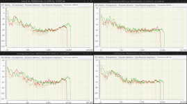
I've done some measurements with Qloud today. I don't know how to use REW though I would be happy to learn, if it will help.
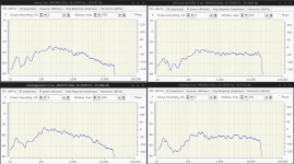
Here are the graphs. No averaging, just a single point. Vertically, all measurements are taken from the center of the 3 module array. No crossover, just the line array.
Legend:
1.0m no eq | 1.0m w/ eq
-------------------------
2.5m no eq | 2.5m w/ eq
I've done some measurements with Qloud today. I don't know how to use REW though I would be happy to learn, if it will help.
Here are the graphs. No averaging, just a single point. Vertically, all measurements are taken from the center of the 3 module array. No crossover, just the line array.
Legend:
1.0m no eq | 1.0m w/ eq
-------------------------
2.5m no eq | 2.5m w/ eq
Attachments
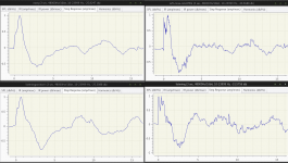
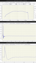
Well I don't know how Qloud renders an IR so it's a bit harder to judge for me. There are a lot of choices for the software to show an IR. I'm pretty used to seeing the REW ones.
This was a single speaker? To judge it we need a single speaker. If this is a single one there are some strange things going on.
This was a single speaker? To judge it we need a single speaker. If this is a single one there are some strange things going on.
Last edited:
Well I don't know how Qloud renders an IR so it's a bit harder to judge for me. There are a lot of choices for the software to show an IR. I'm pretty used to seeing the REW ones.
This was a single speaker? To judge it we need a single speaker. If this is a single one there are some strange things going on.
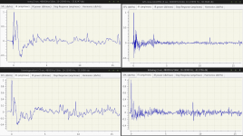
No thats the whole array. I'll try to do a single speaker tomorrow. I agree, that would be horrible for a single driver!
But this was one array firing right? One driver will tell us if it's got a clean impulse, the above measurements are not particularly clean. The STEP, the double peaks.
If that was one array, it doesn't surprise me it's sounding fuzzy up high.
If that was one array, it doesn't surprise me it's sounding fuzzy up high.
To add to the above, the 2.5 m measurements look better than the close results proving the point earlier in this thread.
Yes, this was a single "mini-array" from the floor (not to ceiling, subjectively worse sound with the speakers going to the ceiling) of 24 drivers.
Thanks for your help debugging this wesayso. I am a huge fan of your build and appreciate talking to someone with firsthand experience with a very similar speaker.
As to discussion surrounding the issues of CTC spacing, listening distance from the array... although I don't agree with the Edge simulations (based on theory and practical experience), they force us to ask important questions about why the CTC dimension matters (for circular drivers). I mean, we could just put a handful of speakers evenly spaced floor to ceiling if it didn't matter at all...
I would suggest (and I think Wesayso will suggest the same) is to go back to the floor-to-ceiling setup and work on the EQ. Wesayso can help you there. Get better measurement tools. REW or HolmImpulse are excellent. I know a lot of people prefer REW here, but Holm is also very good and very easy to use.
I'm listening to my arrays right now and the sound could not be better. It just appears out of thin air, excellent depth, tonality is dead on (thank you DRC), couldn't really ask for more. Time to sit back and enjoy.
I'm listening to my arrays right now and the sound could not be better. It just appears out of thin air, excellent depth, tonality is dead on (thank you DRC), couldn't really ask for more. Time to sit back and enjoy.
Last edited:
Yes, this was a single "mini-array" from the floor (not to ceiling, subjectively worse sound with the speakers going to the ceiling) of 24 drivers.
Thanks for your help debugging this wesayso. I am a huge fan of your build and appreciate talking to someone with firsthand experience with a very similar speaker.
As to discussion surrounding the issues of CTC spacing, listening distance from the array... although I don't agree with the Edge simulations (based on theory and practical experience), they force us to ask important questions about why the CTC dimension matters (for circular drivers). I mean, we could just put a handful of speakers evenly spaced floor to ceiling if it didn't matter at all...
Multiple reasons for that I suppose. For instance, you've got to ask yourself the question how the driver plays the higher frequencies. Most (if not all) full range speakers go into a more "bending mode" like state at the top end, not piston like behavior that a little tweeter can still have. Not all of the cone area plays those higher frequencies. So there will be differences between drivers and cone materials etc.
I believe multiple 3.5" and smaller drivers will have an advantage over bigger drivers. Look at it as anti-aliasing in graphics. More drivers is a potential for a smoother pattern up top. I prefer to use the drivers with the cleanest IR to start with. Your Vifa will probably do OK there, at least if it resembles it's family members. A single driver measurement will show that.
Personally I didn't want crossovers to reach my goal. Do I hear a difference between my arrays and a couple of studio monitor speakers? Yes I do, I couldn't believe the amount of high frequency I heard on a pair of those in nearfield listening. But that didn't make it more pleasing to me.
I prefer my arrays, nothing stands out and it sounds more like real life music and sounds to my ears. Something like the use of a tambourine in a song is shockingly real.

Am I missing something at the top end? Maybe/probably, but I wouldn't want to miss the coherency advantage to gain that back. One day I'll play with super tweeters above 10-13 KHz. 😀 (no budget right now)
I'm very curious about the difference in sound you've perceived between the short array and the longer one.
You won't believe the different sounds I've heard my arrays play. Some of those sounds would make me give up on this concept all together (run, Forrest run!). I did recognize some of the prejudice I've read of arrays in some of those experiments. So the way you correct the speakers will have a rather large effect on the sound(s) heard. It's easy to blame the speaker type. It's a bit more work to get it as right as possible (if there is such a thing 🙂) for you with your setup.
Do you want to try that? I'll try and help you get there. I'd suggest using REW, for one reason only, I've spend a lot of time with REW's plots and got a better handle on it, on what it shows and how. Holm no doubt will be good for the job too but it might present the data a little different. We'd have to switch to FIR correction with latency though.
Last edited:
single driver measurements
tc6wd (used in the arrays - cheap one) vs tc6fc00 (neo expensive one, my fave of the tc6)
both measured at around 2"... think the crazy dip on the tc6wd is an artifact of the close measurement (baffle diffraction?), yet it didn't show up on the other one.. different enclosures though (fc had a spherical enclosure)
Attachments
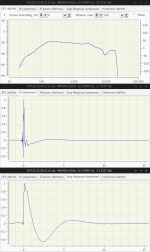
I am pretty sure that the dip is just baffle diffraction null. Those do get very deep with spherical baffles/"boxes". You check that with Edge simulation!
This is from Linkwitz Diffraction from baffle edges
This is from Linkwitz Diffraction from baffle edges
The FC was on the spherical baffle if I read the description right 🙂

A full sphere should do pretty good though, is it completely spherical?
A full sphere should do pretty good though, is it completely spherical?
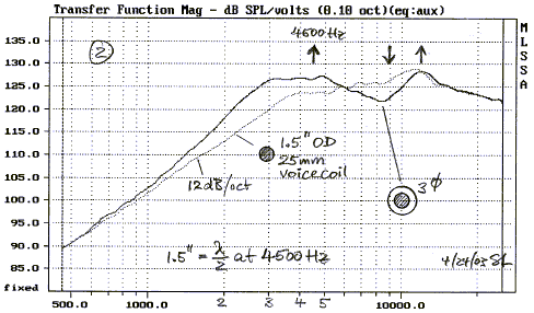
The limitation with The Edge is that it assumes all drivers are completely rigid radiators, which isn't the case for real drivers unless they are operating below their cone breakup node (below a couple kHz). I think it also assumes they are planar instead of conical. The implication is that the off-axis response of a driver compared to on-axis response in The Edge is not quite the same as real life. It also doesn't consider the 'cavity effect' which is edge diffraction due to the cone cavities of other drivers. Despite this it is still very useful for comparing different driver layouts on a baffle.Compelling evidence. I will play with The Edge and report back. Is it modeling the performance correctly? Observations, or rather simulations, are not matching theory. So, the theory needs to be changed to explain the simulation or we don't understand the modeling or there is an error in the simulation.
In real life you'd have to make sure your measurements aren't influenced by room effects. This probably means hoisting the array meters up in the air in a large open space and gating your frequency response measurement appropriately. If you measure in a room then the measurements can only be accurately compared above the gating frequency and you have to be dead certain that the position of the speakers and mic are exactly the same in both cases.
When I get some time I'll take some measurements of my 2-way CBT array. Have you read Don Keele's AES paper from 2015 on the time and phase behavior of a CBT?
Thanks for the tip on the latest Keele Paper. Very accessible paper like his other ones on CBT. I found this paper disappointing in its lack of content. Weesayso will not get his CBT Step Response even from the7th(?) paper by the inventor of the CBT.
In real life you'd have to make sure your measurements aren't influenced by room effects. This probably means hoisting the array meters up in the air in a large open space and gating your frequency response measurement appropriately. If you measure in a room then the measurements can only be accurately compared above the gating frequency and you have to be dead certain that the position of the speakers and mic are exactly the same in both cases.
I realize you're talking about comparing two different arrays in the story above, but the suggested measurement method is damn near impossible for all of us. And we wouldn't have to do it like that, only if we want to compare two theoretical cases.
The suggested method is valid if you would want to produce a speaker with a universal correction. Most of us building these arrays do know we need EQ. We also have and use a room to host the speakers. Maybe even use nearby walls to our advantage. The OP certainly does. With frequency dependent windowing we can go a long way to correct the speaker at the listening position within that room. Of coarse we can't get rid of the room completely, even with FDW but with enough effort we can learn to "read" the room.
I never treated my speakers separately from the room. They work together to do what I want them to. Measurements taken on different days overlay with precision. In my opinion gating within a room is a flawed concept compared to the frequency dependent windowing method. But I'm not talking about the FDW introduced in the current REW (too smoothed). Of coarse I do use gating, just not to base any EQ decision upon. Only for learning my room/speaker integration and behavior and check my results.
We have the advantage as DIY-er to get the results tailored to the room you are in. Why not use that advantage. EQ and FIR alone won't get you those best results. But if you're willing to work at it you can get excellent performance within the room. Move the speakers or change something big in the room and you'd have to start over though.
An example; 2 measurements taken on different days. One of them (the purple one) had a conjugation network in place to correct the rising impedance at higher frequencies:

These measurements were taken without FIR correction, only pré-EQ. Smoothing is 1/48, no gating.
The pré-EQ:

But they do show measurements like this are perfectly reproducible. That doesn't mean they will not change when I move the mic an inch, that's not the point here. I did not work hard to get the mic exactly in the same position, I always use a stereo pair measurement to line up the IR peaks at the mic position, that was all. The mic was pointed about ~ 30 degree up, that's just a loose adjustment.
What I'm saying is that when playing with this type of array we know in advance we need correction. Rather than correct the speaker by itself it's perfectly possible to correct it within your room. You do need to invest time to learn your room and optimize it for better results. We are not after a universal "one correction fits all" solution.
Last edited:
Thanks for the tip on the latest Keele Paper. Very accessible paper like his other ones on CBT. I found this paper disappointing in its lack of content. Weesayso will not get his CBT Step Response even from the7th(?) paper by the inventor of the CBT.
I'll look a bit harder for it, I didn't see it on the busy site from Don. Maybe I just missed it, not hard to get lost there 🙂.
Or is it only available in the AES library?
Last edited:
- Status
- Not open for further replies.
- Home
- Loudspeakers
- Multi-Way
- TC6WD (PE buyout) Line Array - Lessons Learned