Now the volume is 24" x 20" x 9" no what about 71 litres or 2.5 cubic feet. Quite a bit smaller than my last layout. The last one was 25 3/4" x 30 5/8" x 9" or 116 litres (4.1 cubic feet)
Whoa - that's a huge difference.
Mark, if you have the time (and the spare wood!), it might be interesting to find out how the Trio8 TH compares to a vented, 4th order or 6th order BP alignment with the same drivers that occupies the same or less net volume.
Hi Brian.
You come up with the box design and I will knockt off. I have some other jobs to do. Bipole surround, fullrange using EL70's and SDX7's, and a UNHORN4 using TRIO12's. So get in line buddy!
Your idea will not take to long. But save the time and read Geedes paper on bandpass designs. I read it so long ago, but if I remember correctly he only got 7db gain from the box. This should get close to 9db gain. Rember this is not a tapped horn but a bandpass/horn hybrid (I think anyway).
That's my trick for making such a small box work at such a high efficiency at least according to the modeling. Now I have another prototype to play with.
Mark
Mark
You come up with the box design and I will knockt off. I have some other jobs to do. Bipole surround, fullrange using EL70's and SDX7's, and a UNHORN4 using TRIO12's. So get in line buddy!
LOL. Trio12s, eh? I better not add to your workload then - 'cause I'd LOVE to hear your feedback on those drivers 🙂. The only ones more interesting specs-wise is the Earthquake SWS-12X with its published 31mm Xmax, available at around the same price from SonicElectronix - see Earthquake Sound SWS-12X (Black) (sws12x) 12" Subwoofers Car Subwoofers Car Audio Car Audio, Video, & GPS Navigation - Sonic Electronix . It's shallow profile should provide a bit more flexibility wrt box design, and it is more efficient, but whether that 31mm Xmax spec for such a shallow driver is actually realistic is another matter 🙂.
But save the time and read Geedes paper on bandpass designs. I read it so long ago, but if I remember correctly he only got 7db gain from the box. This should get close to 9db gain. Rember this is not a tapped horn but a bandpass/horn hybrid (I think anyway).
I typically avoid designing high-gain bandpass alignments in any case. What's the target F3 point of your Trio8 design, btw, and it's 2*PI passband efficiency?
Hi Brian
The TRIO12's and the specs are conservative. It is a very well made driver. And price wise I think it is cheaper.
As for the Earthquake driver I've ran it through WinISD and Driver Parameter Calculator and it doesn't fair so well. Over stated SPL to begin with as 2.83 volts is more than 1 watt through 6 ohm nominal impedance.
Mark
Mark,
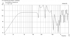
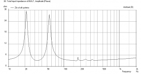
I've converted your picture to an AkAbak script. The result is encouraging. See the attached images. One shows AkAbak's sound pressure measurement with the drivers at maximum rated power (200 watts each), the other shows the impedance curve.
The lowest impedance is 3.2 ohms, so a 2 ohm capable amplifier rated at 300 to 400 watts into 4 ohms would be suitable.
The system is power limited down to 26 Hz, below which it is excursion limited. Based on the driver Xmech figure it should handle up to about an 80 watt amplifier without excursion damage, but a high pass filter will be essential if you want to run high power.
I'm looking forward to the in-car and in-lounge measurements.
Attachments
Mark,
I've converted your picture to an AkAbak script. The result is encouraging. See the attached images. One shows AkAbak's sound pressure measurement with the drivers at maximum rated power (200 watts each), the other shows the impedance curve.
Damn - that looks nice. 2*PI or 0.5*PI? What's the output look like at 2.83V?
Now this is encouraging! Thanks for taking the time to work this out Don. And for posting your findings. I may not be completely crazy after all eh?
After David McBean made it possible to export the Hornresp data directly to AkaBak it became much easier to get the crazy program to work. I thought for a couple pf days when I was working how to lay this out so that I could respect the actual driver placement. None to easy of a task mind you. But I think this is the best setup I can come up with.
The box is dry and I will have some time this weekend to mess around with it and take measurements. I'm expecting this one to really behave itself. It is crazy to think that the lst box with the block moving around in the end had quite a visceral impact when used in room. This one with no obstructions should be a real butt kicker.
Can't wait! Just gotta get me some closed cell weather stripping tape. Then I can fold up the top on the box and take it for a test spin.
My boys both commented on the more open and articulate sound with the previous box. I missed the real bottom end I never really got out of it. I was hoping for gut smacking 30 hz. But when I got close I thought it was a design compromise that robbed me of my prize. An ill place block of wood will get you every time! No more quicky jobs. This has to work the first time. I had a hell of a time taking the box apart. So this one is put together like a cabinet maker should. ( right the first time!)
Mark

Here are some figures Brian. Maximum power is first.
Mark
This is interesting - Abakak is predicting for your design an output of just over 113dB if I'm reading the graph correctly. A simple vented enclosure with those drivers should be able to achieve something similar. However HornResp seems to be suggesting somewhat higher output.
Looking forward to the results in any case!
Hi Brian
I'm a bit stumped by something here. I have quite a few programs that I can model these drivers in. Bass Box gives a maximum SPL of 114 db. WinISD gives 107 db. Stick the 6 db corner loading on either one and you may get a true corner loaded SPL specification.
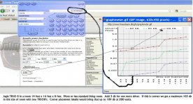
The JAVA applet on the LINEAR TEAM site gives me a maximum corner loaded in a standard 14' x 16' x 8' living room 100 db. Add a second driver and you get 103db. Corner load the cabinet and 109db.
Hornresp gives me 128db corner loaded.
They are programs. Only as good as the moron typing in the data I know. But I'm using the same Thiele/Small specs for them all. So heck if I know. What I know for sure is this. Hornresp predicted 108 db/watt for UNHORN1 in a car or 1/8th space. And that is what I got. So maybe I trust Hornresp?
Mark[/ATTACH]
I'm a bit stumped by something here. I have quite a few programs that I can model these drivers in. Bass Box gives a maximum SPL of 114 db. WinISD gives 107 db. Stick the 6 db corner loading on either one and you may get a true corner loaded SPL specification.
The JAVA applet on the LINEAR TEAM site gives me a maximum corner loaded in a standard 14' x 16' x 8' living room 100 db. Add a second driver and you get 103db. Corner load the cabinet and 109db.
Hornresp gives me 128db corner loaded.
They are programs. Only as good as the moron typing in the data I know. But I'm using the same Thiele/Small specs for them all. So heck if I know. What I know for sure is this. Hornresp predicted 108 db/watt for UNHORN1 in a car or 1/8th space. And that is what I got. So maybe I trust Hornresp?
Mark[/ATTACH]
Attachments
Last edited:
Damn - that looks nice. 2*PI or 0.5*PI? What's the output look like at 2.83V?
The output at 2.83 volts is about 92.5dB.
The AkAbak default is infinite baffle (2*PI). If you want free space (4*PI) you need to specify the baffle dimensions. If you want 1*PI or 0.5*PI you need to define some reflectors to represent the floor and walls.
This can get complex, but it does allow accurate modelling when calculating, for example, baffle step and floor reflection compensation networks. (Akabak models electrical components as well as acoustic components.)
The output at 2.83 volts is about 92.5dB.
Ah - quite similar to HornResp. I notice that the peak voltage in your model is different to the one Mark used in HornResp, which would explain a good portion of the discrepancy in peak output as well.
At 92.5dB, my spreadsheet suggests that the output is just one dB higher than a simple vented alignment using the same drivers (wired in parallel).
Hello Don and Brian
I think the difference between Don's figures and mine are that he is using 3.6 ohm's and I'm using 4 ohms. It is probable that both are incorrect as when a horn is functioning it usually has a little higher impedance. At least that is what I found on the other two horns I measured.
One other point for some thought is this. This type of horn with a grossly undersized mouth cannot function in a 2 Pi or 4Pi environment anywhere near the efficiency that you will se it have when it is in a 1 Pi or .5 Pi area. Danley's designs are similar in that the pro sound horns are designed to be setup in groups where the horn mouths mutually couple. This horn is definitely designed for a smaller acoustical space than a long wall and a ground base that a 2 Pi environment provides.
I understand that any driver and box combination will see a gain in it's passband when given reinforcing reflections. But we are circling back to the arguement found at the beginning of this thread that the design is to short to work or the mouth is to small.
The entire premise of this thread is the smallest horn possible purpose designed for a given acoustical environment. The little horn functions as predicted and measured in a car or in a tight corner. If you put it in a more or less 2 Pi environment it plummets to 92 db/watt instead of 108 db/watt. I measured this at 100 hz in the longest wall of my home next to a staircase that went down from the floor level the sub was sitting on 16 feet from any corner. I measured at 100hz on purpose to try to negate any reflections because of the wavelength of 100 hz is approximately 11' 3".
At the same frequency in the car (again chosen because it is just at the beginning of the boundary reinforcement available in most automobiles) I get 108 db/watt.
My only point in all this bantering is that unlike a direct radiator being placed in successively smaller acoustical environments getting reinforcement from each new boundary. A horn gets the reinforcement and an efficiency gain because it is designed to couple to a given acoustical environment. The design element in question is usually the horn mouth size. The larger the mouth the more successfully it can be coupled to almost any environment.
Keep in mind for a horn to play with full efficiency at 30 hz in a 2 Pi environment the mouth has to be enormous. The half wavelength of 30 hz is 18' 9" imagine a horn mouth at 9' 4 1/2" on a side. But that is what is where we would have to go to get full efficiency all the way down to 30 without 2 Pi boundary reinforcement.
Brian is your spreadsheet publicly available?
And do you have any comment on the WinISD figures for the room size I calculated two 8 inch drivers for? It seems from practical experience to me ( I have installed and worked with quite a few sound systems over the years ) to be rather close to reality. I have to find the raw formula to convert volume displacement into SPL. I know I have used it before but computer programs are making me lazy!
Mark
The little horn functions as predicted and measured in a car or in a tight corner. If you put it in a more or less 2 Pi environment it plummets to 92 db/watt instead of 108 db/watt.
The vented design should experience the same gain. I take your point about the horn though - in fact it should show even MORE gain nearer to the cutoff frequency of the horn as the space gets smaller. OTOH, a car's trunk or cabin is actually an enclosed space, and this may have an adverse effect. All admit that this is something I've heard, not experienced with my own measurements.
Brian is your spreadsheet publicly available?
The older version is available off of my website. The new version is not ready for prime-time - in its current state it's the equivalent of a mechanic's car - works great but usually looks like crap 🙂.
And do you have any comment on the WinISD figures for the room size I calculated two 8 inch drivers for?
If it's grossly off, I'd recheck the model. Perhaps you modeled with the drivers in series instead of parallel. I think the earlier versions of WinISD used the same equations I have on my site, so the results should be similar, if not identical to those predicted by my spreadsheet.
I think there's a common misunderstanding arising from the name "tapped horn". It's not really a tapped horn. Calling it a horn implies operation at wavelengths much shorter than the dimensions of the horn. But at the wavelengths we are concerned with here, it's really a "tapped pipe" or quarter-wave resonator. For all practical implementations, the mouth size is far too small to think of it as a horn. And in fact, we consider its true horn mode to be an undesired side effect, to be suppressed by a low-pass filter.
So if it is not a horn, then it is not subject to the same problems that a horn has in a small room / space. It's more accurate to consider it as a class of resonant (vented) enclosure, subject to the same effects in a confined space. So if you know how a vented enclosure will behave in a car, you also have a good idea how a similar response curve tapped pipe will behave.
So if it is not a horn, then it is not subject to the same problems that a horn has in a small room / space. It's more accurate to consider it as a class of resonant (vented) enclosure, subject to the same effects in a confined space. So if you know how a vented enclosure will behave in a car, you also have a good idea how a similar response curve tapped pipe will behave.
Hi Don
Your point is well taken. I was consciously not calling this box a horn for quite a while. It is most definitely not a horn in the classical sense of a true gradual expansion, driver diaphragm to surrounding air impedance matching transformer that a real horn creates. I'll have to keep this in mind when I'm typing from now on.
Plain as day it is to short. The mouth is incredibly under sized.
It is a tapered quarter wavelength double tuned resonator. And yep where the mouth side of the enclosure can and does act like a horn we are no longer interested in it's output.
But it is loud and proud. And a bit more efficient than an equivalent vented box. And it sounds good. And I hope to post some pictures of the closed up enclosure this afternoon. Feel like crap right now. Anybody want to take a cold for free. Only slightly used?
Mark
Updates?
Yep
I'm done the dual TRIO8 UNHORN. It kicks some serious butt. Adam went on a little tear this afternoon when I was in Ottawa today and he could not make it hickup in any way shape or form with the rap torture test tracks that he had. I played him some mean Pipe Organ tracks and again the sub played loud and proud with very good authority.
So it works and works well. I'lll get some measurements up. But after this I'm done.
Mark
- Status
- Not open for further replies.
- Home
- Loudspeakers
- Subwoofers
- Tapped Horn For Car