If all you want is loud
Well here is a quick comparison. Both boxes have their strong points. The UNHORN2 Does have low end problems below 30hz. But the comparison is telling.
Here is the 18 inch Maelstrom in all it's glory. 1500 watts of power sucking
muscle.
Here is the TRIO8 500 watts of power with almost the same muscle.
This is why we make more complicated boxes. Problem lies in the ability to go down as low. But compared from the same areas they are pretty darn close. At one third the power. And the Maelstrom box is bigger. It is true that if you tailor the response to almost the same drop off the Maelstrom box gets smaller but the power difference remains and the SPL peak narrows giving the UNHORN even greater advantage.
Mark
Well here is a quick comparison. Both boxes have their strong points. The UNHORN2 Does have low end problems below 30hz. But the comparison is telling.
Here is the 18 inch Maelstrom in all it's glory. 1500 watts of power sucking
muscle.
An externally hosted image should be here but it was not working when we last tested it.
Here is the TRIO8 500 watts of power with almost the same muscle.
An externally hosted image should be here but it was not working when we last tested it.
This is why we make more complicated boxes. Problem lies in the ability to go down as low. But compared from the same areas they are pretty darn close. At one third the power. And the Maelstrom box is bigger. It is true that if you tailor the response to almost the same drop off the Maelstrom box gets smaller but the power difference remains and the SPL peak narrows giving the UNHORN even greater advantage.
Mark
Some more info before I go to sleep
Here is the input screen for the latest design as built with driver positions and the mouth that is a bit to small.
Mark
The peak can be tamed with an inductor and or proper stuffing. But with an electronic crossover it is not a big problem. One thing that I will have to investigate further is the low end below horn cutoff. I have been playing it at high levels and it does not bottom out really hard. I'm not sure yet why I'm only driving it with my car amp as of now. At 3 ohms I have around 40 watts clean power. But it is louder than I care to take it. Test tones are excruciatingly loud. So if the weather co-operates I will do some outside testing and some inside testing this weekend.
Mark
Attachments
We did some listening today, heres the verdict.
Although we never passed 5w on the measurements, we peaked again at 112db in car. This toyota matrix has a nasty resonance around 75~80hz and it seems to muddy up anything that gets played in that range. Marks front speakers leave a lot to be desired when trying to compete with the higher spl levels of the unhorn2. the nice thing is, this box has a natural rolloff/highpass around the 30hz range, and unlike the old unhorn, it didn't stuggle in those ranges, instead it just passed over. We only had about a half hour to listen to the setup.
Overall impressions, After listening to this and getting back into my cousins g5 with the 7.1 pioneer system and 10 inch 200w powered sub, i think the size of the vehicle is really whats causing so many problems when measuring this thing. i'd like to see what it sounds like on a separate amp so we can have some gain control and a little more fine-tuning with the crossover. Limiting it it 80hz with the high pass added a little bit more refined sound, but still that 80hz peak was noticeable. i think a ~70hz integration would be better, but thats just me. Do note that im not one to listen to my stereo with the bass at lower volumes. i prefer to add a little more authority than is actually there, or required in my music.
This sub sounded absolutely amazing on 5w playing some Lynard Skynard.
I think if mark invested some money into his mid/high's the overall impressions would have improved dramatically as well. This car just isnt set up for really high spl reproduction, just decent daily levels and a little louder than most people would listen to regularly.
Tapped horn for car
It seems you've done a great job on this latest sub, Mark. I realize the thread is titled "Tapped Horn For Car," but how does this sub do in a home environment? Limits for HT use? Better for music? SPLs along a wall, in a corner, or with paired units? Cars and homes are different kettles of fish, and a sub that's good for one, isn't necessarily good for the other.
Most importantly, you've posted a number of things about your sub's efficiency and useable bandpass, but beyond technical parameters, what about the quality of its sound in a home? How "musical" do you think it is? How do you think it compares to other horn subs--tapped or otherwise?
A lot of us audio-enthusiasts are less sanguine about modeling and test results than listening results. Not that technical issues are any less important, but when surfing the web for a sub to build, a lot of us think in terms of ease of construction, dimensions, actual quality of sound, and of course, cost-effectiveness.
What does your sub do best, and what's its greatest "advantage?" That is, why should a guy build your design rather than another?
Cheers, Bill
Well here is a quick comparison. Both boxes have their strong points. The UNHORN2 Does have low end problems below 30hz. But the comparison is telling.
I noticed that you used 1xPI for your TH model. I think 2xPI would be a better choice if you want to compare output capability with a sealed or vented alignment modelled by WinISD.
Well here is a quick comparison. Both boxes have their strong points. The UNHORN2 Does have low end problems below 30hz. But the comparison is telling.
Well, I hate WinISD (graphs way too horizontally compressed for my taste, and it just looks so horribly un-Maclike), but it wouldn't occur to me to use an undersized vented box for the Mael-X for the car. A sealed box meshes nicely with a car's transfer function.
Here is the TRIO8 500 watts of power with almost the same muscle.
Except that from probably ~70 Hz down, the Trio8s are going to be well over xmax! I base that off of modeling a 4th order BP box and assuming that a horn will be a little better.
As it happens, I have both a Mael-X and a pair of Trio8's, so it might be interesting to do as a comparison.
It sucks measureing loudspeakers
I do believe my two young friends managed with my little undersized amp to fry the inner driver of the UNHORN. All the measurements that I have done are nothing close to what we were getting in the car test. So I must make a couple of access panels and check things out thoroughly.
As for the comparison between the UNHORN and the Maelstrom. I should pay a little more attention to the programs that I'm using sometimes. I uploaded the 2 Pi results. Yes it makes things look a little worse. But I'm not all that unhappy. Were still close at 1/3rd the power input. And almost the same size box. And come on guys were comparing an 18 to two 8's. Lets be fair here. The 8's need some real competition!
Harms1
What this box does well is legion. It gives you kick and impact that is in the you have to hear it to believe it category. Good horns excel at this no matter what design form. It does play down low enough to be satisfying. It has good output to 35 hz tested outside and in the middle of a small room. I've tried big pipe organ orchestral bass drum ala Reference Recordings and Telarc. I've tried the old Dorian recordings in all shape a sizes. This sub can really kick butt. I find it tunefull. You can follow complex bass passages with great clarity. That is not always easy to do with most subs. If there is little or no low end in the program material you get little or no bass. Men sound like men when listening to singers. Not overgrown gorillas. So all in all this box seems to be behaving itself. It works like a good horn.
Why build it? Well sound quality is one important part of the equation. Depth of bass that is still clean and clear is not something normally heard from a sub-woofer. Ease of construction? Well it is not that hard to put together. If anyone is interested I can put together a bit of a tutorial. There is a way to get rid of that peak in the response if you build it with an optimal mouth. The box takes on a bit of a lumpy shape near the mouth but not that bad. I just wanted to see what would happen if I made it fit into a rectangular form factor. The results are quite pleasing.
As for measurements inside and in the corner and wall positions. When I replace the driver I will do the testing. It's the same old problem. Small amps kill drivers and big amps treat them kindly. I think it is time to upgrade my car stereo. A good 200 watt sub amp will never clip at the levels I listen to. The head unit I have must have been clipping at some point in the boys torture test. Right now I have a driver that is rattling and giving me distortion measurements that are around 10%. Something is definitely amiss as this is not the sound I was listening to for the better part of a week.
Alls fun and games until someone fries a woofer.
Mark
Attachments

I do believe my two young friends managed with my little undersized amp to fry the inner driver of the UNHORN.
I'm not a believer in the ability of small amps blowing woofers. I used to use a 60Wx2 to drive my two 1200GTis (rated @ 600W, 1kW peak) at pretty high levels for years without any failure.
Heat buildup and over-excursion - that's what destroys woofers. I wouldn't be surprised if you open up that box and see one of the drivers is mechanically damaged - perhaps a creased cone or torn spider.
I uploaded the 2 Pi results. Yes it makes things look a little worse.
What about the displacement graph at the same 400W power level? I think that might be of interest as well.
Hi Brian
You may very well be right.
But I to have had drivers come back from clients that were baked by small amps clipping into DC for long enough to bake voice coils. And I have done exactly that using a small amp to do test and measurement. My current test amp is a parasound HCA-1000A. It does not run out of steam.
I have an impedance plot that tells much about what is happening to the driver on the inside. It was not that way prior to the boys torture test. So although I'm a bit unhappy that i killed a driver I'm pretty sure that I know why. We never hit over 5 watts into the box but they were trying to get the drivers to unload below the box system resonance. I really did not hear anyhting going wrong but that may not have been the actual case.
Any loudspeaker played below it's pass-band loud enough will give up the ghost if you try that to aggressively. A horn is particularly susceptible to this problem. No free lunch when dealing with fancy boxes. Great efficiency comes at a price. It's just that with a bit of care you can have quite a bit of your lunch free from compression and distortion. I'm not throwing in the towel anytime soon.
Mark
Attachments
Last edited:
We never hit over 5 watts into the box but they were trying to get the drivers to unload below the box system resonance.
They were getting 112dB with just 5 watts?
To actually kill one of the drivers with just 5 watts - that sounds a bit unrealistic. And your TH's got significant out of band noise just above its passband - that should have amplified any distortion being produced. Surely it would have been very audible if the amp was being driven over its limits.
I think it would be interesting to see what's actually happened to that inside driver.
I might have missed this - what's the net volume of the box?
I do believe my two young friends managed with my little undersized amp to fry the inner driver of the UNHORN. All the measurements that I have done are nothing close to what we were getting in the car test. So I must make a couple of access panels and check things out thoroughly.
I've been worried this would happen.
Here's my first tapped horn for the car.

And here's my second.
The reason that the second box is hideously complex is to get "real" low bass in the car. A tapped horn unloads the driver below one-quarter wavelength, so it's fairly easy to blow the driver up without a infrasonic filter.
And it's hard to tell that the woofer is dying, because the reduction in 2nd and 3rd harmonic distortion can mask the signs of a failing woofer.
Summary:
Well, this has been educational. I've learnt more about Akabak, and opened up a couple of areas of investigation:
- I've come up with a construction method for simplifying small bass horn construction and allowing constant radius bends. I'll start a new thread with it.
- I'm going to investigate one of the ideas of the Unhorn design, namely multiple drivers at different positions on the pipe. There is no free lunch, but it might be possible to balance out response irregularities caused by shorter than optimum pipe length. It might also allow smaller than optimum internal volume, so that 2 drivers do not require twice the pipe volume. Hoffman's Iron Law still applies, but modern drivers such as the DX7 make the compromises more acceptable. The ideal goal would be a significantly smaller than usual cabinet that has a flat response, so doesn't require equalisation.
(Or, for car use, has a 12 dB/octave falling response that nicely matches cabin gain.)
Yep, this works very nicely. That's how I'm able to squeeze so much bandwidth out of the triple eight.
Another thing that you might want to try is using two woofers, with different line lengths, that feed into the same mouth.
I don't have any pictures, but imagine a "snail" horn, but with dual woofers and dual lines, each with a different length, that meet at a halfway point.
Does that make sense?
Staggering the line lengths staggers the impedance dips, and the maximum excursion. So basically you don't end up in a situation where both woofers are running out of excursion or power handling simultaneously.
It's a bit complex to build, but should raise your power handling by 50% or so. It's easier on your amplifier too.
Here's the Akabak model. It's using a pair of Dayton 5" woofers.
System 'S1'
|DATA EXPORTED FROM HORNRESP - RESONANCES NOT MASKED
|COMMENT: th-mini clone, xara file is on other pc, 5/10/09. This one w/MCM 55-2421x2
|================================================= ================================================== =====
|REQUIRED AKABAK SETTINGS:
|File > Preferences > Physical system constants:
|Sound velocity c = 344m/s
|Medium density rho = 1.205kg/m3
|Sum > Acoustic power:
|Frequency range = 10Hz to 20kHz
|Points = 533
|Input voltage = 31.62V rms
|Integration = 2Pi-sr
|Integration steps = 1 degree ... 1 degree
|Integration method = Cross
|================================================= ================================================== =====
Def_Const |Hornresp Input Parameter Values
{
|Length, area and volume values converted to metres, square metres and cubic metres:
Rg = 0.01e-0; |Amplifier output resistance (ohms)
S1 = 19.4e-4; |Horn segment 1 throat area (sq cm)
S2 = 38.7e-4; |Horn segment 1 mouth area and horn segment 2 throat area (sq cm)
S3 = 70.4e-4; |Horn segment 2 mouth area and horn segment 3 throat area (sq cm)
S4 = 316.5e-4; |Horn segment 3 mouth area and horn segment 4 throat area (sq cm)
S5 = 412.8e-4; |Horn segment 3 mouth area and horn segment 4 throat area (sq cm)
| second leg of the tapped horn
S6 = 19.4e-4; |Horn segment 3 mouth area and horn segment 4 throat area (sq cm)
S7 = 38.7e-4; |Horn segment 3 mouth area and horn segment 4 throat area (sq cm)
L12 = 10.2e-2; |Horn segment 1 axial length (cm)
L23 = 80.0e-2; |Horn segment 2 axial length (cm)
L34 = 10.2e-2; |Horn segment 3 axial length (cm)
L45 = 4.0e-2; |Horn segment 3 axial length (cm)
| second leg of the tapped horn
L67 = 10.2e-2; |Horn segment 3 axial length (cm)
L73 = 120.2e-2; |Horn segment 3 axial length (cm)
|Parameter Conversions:
Sd = 108.2e-4; |Total diaphragm area for 2 parallel drivers (sq cm)
}
|================================================= ================================================== =====
|Network node numbers for this tapped horn system:
|0-Voltage-1-Resistance-2----------
| x x
| --Driver1------ ---------------------------
| x -Driver2-------------- x
| x x x x
| 8-Segment-9-Segment-10-Segment-11-Segment-12-Segment-13-Segment-14-Radiator
|================================================= ================================================== =====
Def_Driver 'Driver'
Sd=54.1cm2
Bl=5.04Tm
Cms=9.34E-04m/N
Rms=0.76Ns/m
fs=74.9Hz |Mmd = 1.69g not recognised by AkAbak, fs calculated and used instead
Le=0.73mH
Re=6.4ohm
ExpoLe=1
System 'System'
Resistor 'Amplifier Rg'
Node=1=2
R={Rg}
Driver Def='Driver''Driver 11'
Node=2=0=9=11
Driver Def='Driver''Driver 21'
Node=2=0=14=11
Waveguide 'Horn segment 1'
Node=8=9
STh={S1}
SMo={S2}
Len={L12}
Conical
Waveguide 'Horn segment 2'
Node=9=10
STh={S2}
SMo={S3}
Len={L23}
Conical
Waveguide 'Horn segment 3'
Node=10=11
STh={S3}
SMo={S4}
Len={L34}
Conical
Waveguide 'Horn segment 4'
Node=11=12
STh={S4}
SMo={S5}
Len={L45}
Conical
Radiator 'Horn mouth'
Node=11
SD={S5}
Waveguide 'Horn segment 5'
Node=13=14
STh={S6}
SMo={S7}
Len={L67}
Conical
Waveguide 'Horn segment 6'
Node=14=10
STh={S7}
SMo={S3}
Len={L73}
Conical
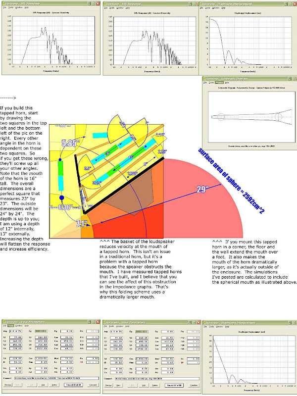
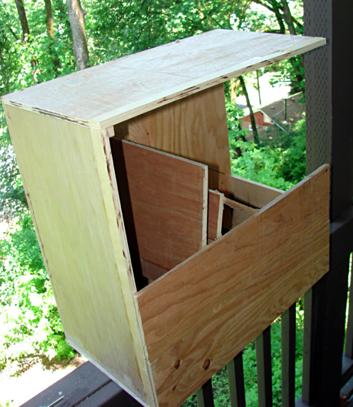
Here is a construction drawing. Full scale with some cleaner lines drawn in.
An externally hosted image should be here but it was not working when we last tested it.
Hmm... that looks a lot like the TH design I recently stumbled across while playing with HornResp. Basically S1>>S2, with the driver placed at S2, then you expand as normal. The expansion at the other end of the throat tends to flatten the response - well, at least in the sims. I've yet to build one to confirm - because I can't find a way to efficiently fold it like you did 🙂.
Here's an example, using one MCM 55-3421. Notice the predicted output for just one 8...
Attachments
OK, I think I figured out why the woofer went *pop*
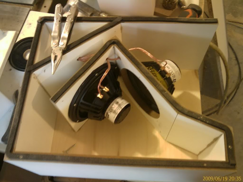
This is your original design. See how the front and the back wave of the woofer is seperated by just an inch? That will make the excursion go crazy, since the woofer is almost completely unloaded.
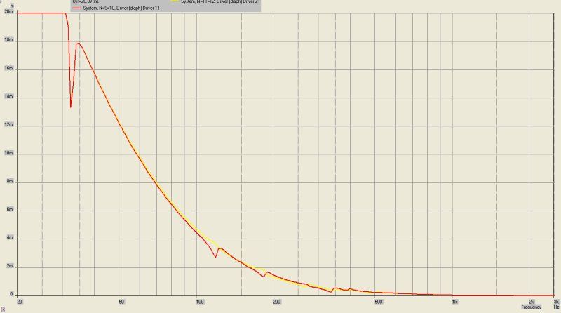
I looked at the pic of your NEW box, and created an Akabak model of it. Here's the simulate excursion. As I feared, the woofer is almost completely unloaded. This simulation is with 100 watts into 8ohms. You can see it won't go "pop" until you get serious output below 50hz. The yellow line is the first woofer, red is the second.
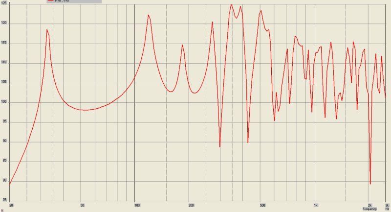
This is the frequency response. Efficiency is high, but frequency response has serious peaks. Akabak models this more accurately than Hornresp. Hornresp can't model multiple woofers in multiple locations, and it can't model a woofer that's arranged the way you've arranged them. Akabak can.
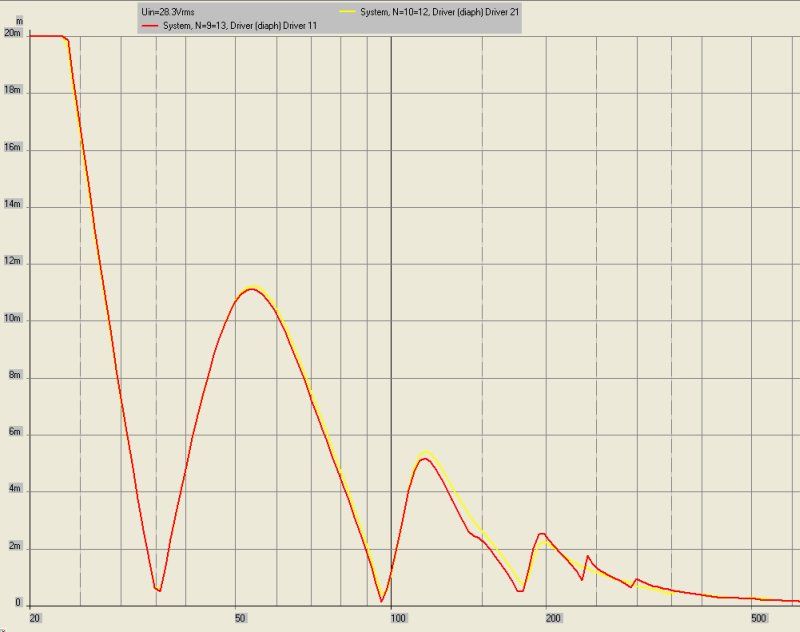
For the sake of comparison, here is the SDX7, but simulated in my "triple 8" box. This is the excursion. With a 30hz subsonic filter, the design will take 100watts before running out of excursion.
Here's the simulated frequency response. Efficiency is lower, but response is smoother.
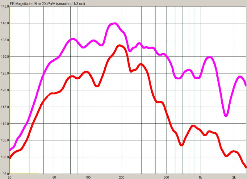
The purple line is the actual measured response of the triple-8 enclosure, with three eights. Note the peak at 180hz, and the dip at 120hz? These are consistent with the Akabak sim, which shows that Akabak is pretty darn accurate.
Here's the Akabak model for your box. I took the dimensions from the pic you posted.
[font="Courier New]
System 'S1'
|DATA EXPORTED FROM HORNRESP - RESONANCES NOT MASKED
|COMMENT: th-mini clone, xara file is on other pc, 5/10/09. This one w/MCM 55-2421x2
|================================================= ================================================== =====
|REQUIRED AKABAK SETTINGS:
|File > Preferences > Physical system constants:
|Sound velocity c = 344m/s
|Medium density rho = 1.205kg/m3
|Sum > Acoustic power:
|Frequency range = 10Hz to 20kHz
|Points = 533
|Input voltage = 31.62V rms
|Integration = 2Pi-sr
|Integration steps = 1 degree ... 1 degree
|Integration method = Cross
|================================================= ================================================== =====
Def_Const |Hornresp Input Parameter Values
{
|Length, area and volume values converted to metres, square metres and cubic metres:
Rg = 0.01e-0; |Amplifier output resistance (ohms)
S1 = 570.0e-4; |Horn segment 1 throat area (sq cm)
S2 = 294.0e-4; |Horn segment 1 mouth area and horn segment 2 throat area (sq cm)
S3 = 147.0e-4; |Horn segment 2 mouth area and horn segment 3 throat area (sq cm)
S4 = 112.9e-4; |Horn segment 3 mouth area and horn segment 4 throat area (sq cm)
S5 = 406.3e-4; |Horn segment 4 mouth area and horn segment 5 throat area (sq cm)
S6 = 541.8e-4; |Horn segment 5 mouth area and horn segment 6 throat area (sq cm)
S7 = 587.0e-4; |Horn segment 6 mouth area (sq cm)
L12 = 55.9e-2; |Horn segment 1 axial length (cm)
L23 = 38.1e-2; |Horn segment 2 axial length (cm)
L34 = 50.0e-2; |Horn segment 3 axial length (cm)
L45 = 28.26e-2; |Horn segment 4 axial length (cm)
L56 = 12.7e-2; |Horn segment 5 axial length (cm)
L67 = 38.1e-2; |Horn segment 6 axial length (cm)
|Parameter Conversions:
Sd = 256.0e-4; |Total diaphragm area for 2 parallel drivers (sq cm)
}
|================================================= ================================================== =====
|Network node numbers for this tapped horn system:
|0-Voltage-1-Resistance-2----------
| x x
| --Driver1------ ---------------------------
| x -Driver2-------------- x
| x x x x
| 8-Segment-9-Segment-10-Segment-11-Segment-12-Segment-13-Segment-14-Radiator
|================================================= ================================================== =====
Def_Driver 'Driver'
Sd=128.3cm2
Bl=8.46Tm
Cms=10.02E-04m/N
Rms=2.09Ns/m
fs=34.0000Hz |Mmd = 1.69g not recognised by AkAbak, fs calculated and used instead
Le=0.75mH
Re=6.40ohm
ExpoLe=1
System 'System'
Resistor 'Amplifier Rg'
Node=1=2
R={Rg}
Driver Def='Driver''Driver 11'
Node=2=0=9=10
Driver Def='Driver''Driver 21'
Node=2=0=11=12
Duct 'Horn segment 1'
Node=8=9
SD={(S1+S2)/2}
Len={L12}
Duct 'Horn segment 2'
Node=9=10
SD={(S2+S3)/2}
Len={L23}
Duct 'Horn segment 3'
Node=10=11
SD={(S3+S4)/2}
Len={L34}
Waveguide 'Horn segment 4'
Node=11=12
STh={S4}
SMo={S5}
Len={L45}
Conical
Waveguide 'Horn segment 5'
Node=12=13
STh={S5}
SMo={S6}
Len={L56}
Conical
Waveguide 'Horn segment 6'
Node=13=14
STh={S6}
SMo={S7}
Len={L67}
Conical
Radiator 'Horn mouth'
Node=14
SD={S7} [/font]
This is your original design. See how the front and the back wave of the woofer is seperated by just an inch? That will make the excursion go crazy, since the woofer is almost completely unloaded.
I looked at the pic of your NEW box, and created an Akabak model of it. Here's the simulate excursion. As I feared, the woofer is almost completely unloaded. This simulation is with 100 watts into 8ohms. You can see it won't go "pop" until you get serious output below 50hz. The yellow line is the first woofer, red is the second.
This is the frequency response. Efficiency is high, but frequency response has serious peaks. Akabak models this more accurately than Hornresp. Hornresp can't model multiple woofers in multiple locations, and it can't model a woofer that's arranged the way you've arranged them. Akabak can.
For the sake of comparison, here is the SDX7, but simulated in my "triple 8" box. This is the excursion. With a 30hz subsonic filter, the design will take 100watts before running out of excursion.
Here's the simulated frequency response. Efficiency is lower, but response is smoother.
The purple line is the actual measured response of the triple-8 enclosure, with three eights. Note the peak at 180hz, and the dip at 120hz? These are consistent with the Akabak sim, which shows that Akabak is pretty darn accurate.
Here's the Akabak model for your box. I took the dimensions from the pic you posted.
[font="Courier New]
System 'S1'
|DATA EXPORTED FROM HORNRESP - RESONANCES NOT MASKED
|COMMENT: th-mini clone, xara file is on other pc, 5/10/09. This one w/MCM 55-2421x2
|================================================= ================================================== =====
|REQUIRED AKABAK SETTINGS:
|File > Preferences > Physical system constants:
|Sound velocity c = 344m/s
|Medium density rho = 1.205kg/m3
|Sum > Acoustic power:
|Frequency range = 10Hz to 20kHz
|Points = 533
|Input voltage = 31.62V rms
|Integration = 2Pi-sr
|Integration steps = 1 degree ... 1 degree
|Integration method = Cross
|================================================= ================================================== =====
Def_Const |Hornresp Input Parameter Values
{
|Length, area and volume values converted to metres, square metres and cubic metres:
Rg = 0.01e-0; |Amplifier output resistance (ohms)
S1 = 570.0e-4; |Horn segment 1 throat area (sq cm)
S2 = 294.0e-4; |Horn segment 1 mouth area and horn segment 2 throat area (sq cm)
S3 = 147.0e-4; |Horn segment 2 mouth area and horn segment 3 throat area (sq cm)
S4 = 112.9e-4; |Horn segment 3 mouth area and horn segment 4 throat area (sq cm)
S5 = 406.3e-4; |Horn segment 4 mouth area and horn segment 5 throat area (sq cm)
S6 = 541.8e-4; |Horn segment 5 mouth area and horn segment 6 throat area (sq cm)
S7 = 587.0e-4; |Horn segment 6 mouth area (sq cm)
L12 = 55.9e-2; |Horn segment 1 axial length (cm)
L23 = 38.1e-2; |Horn segment 2 axial length (cm)
L34 = 50.0e-2; |Horn segment 3 axial length (cm)
L45 = 28.26e-2; |Horn segment 4 axial length (cm)
L56 = 12.7e-2; |Horn segment 5 axial length (cm)
L67 = 38.1e-2; |Horn segment 6 axial length (cm)
|Parameter Conversions:
Sd = 256.0e-4; |Total diaphragm area for 2 parallel drivers (sq cm)
}
|================================================= ================================================== =====
|Network node numbers for this tapped horn system:
|0-Voltage-1-Resistance-2----------
| x x
| --Driver1------ ---------------------------
| x -Driver2-------------- x
| x x x x
| 8-Segment-9-Segment-10-Segment-11-Segment-12-Segment-13-Segment-14-Radiator
|================================================= ================================================== =====
Def_Driver 'Driver'
Sd=128.3cm2
Bl=8.46Tm
Cms=10.02E-04m/N
Rms=2.09Ns/m
fs=34.0000Hz |Mmd = 1.69g not recognised by AkAbak, fs calculated and used instead
Le=0.75mH
Re=6.40ohm
ExpoLe=1
System 'System'
Resistor 'Amplifier Rg'
Node=1=2
R={Rg}
Driver Def='Driver''Driver 11'
Node=2=0=9=10
Driver Def='Driver''Driver 21'
Node=2=0=11=12
Duct 'Horn segment 1'
Node=8=9
SD={(S1+S2)/2}
Len={L12}
Duct 'Horn segment 2'
Node=9=10
SD={(S2+S3)/2}
Len={L23}
Duct 'Horn segment 3'
Node=10=11
SD={(S3+S4)/2}
Len={L34}
Waveguide 'Horn segment 4'
Node=11=12
STh={S4}
SMo={S5}
Len={L45}
Conical
Waveguide 'Horn segment 5'
Node=12=13
STh={S5}
SMo={S6}
Len={L56}
Conical
Waveguide 'Horn segment 6'
Node=13=14
STh={S6}
SMo={S7}
Len={L67}
Conical
Radiator 'Horn mouth'
Node=14
SD={S7} [/font]
Do you have a folding plan for this single 55-3421?
Not yet 🙂. I may end up scrapping the attempt anyway - the result is likely going to be one big-*** box just for an 8" driver...
Well thank you gentlemen for the constructive criticisim
Finally the thoughts come in.
John thanks for the AkaBak models.
Brian if you want a fold just say the word.
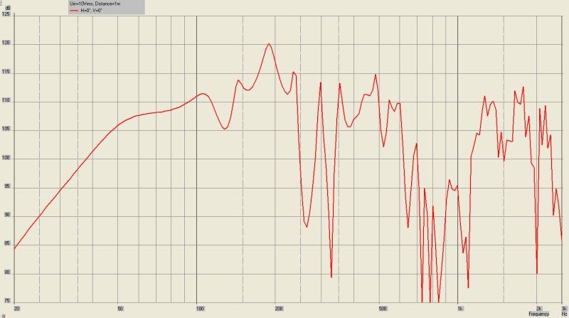
As for frequency response. It does not measure anything like the modeling. In fact it completely baffles me as to how the heck I'm getting what I was getting last night. The measurements were done outside on level ground 30 feet from the house in my back yard. It was a gracefully falling response at 3 db/octave from 20 hz down to 200 hz. The peak was at the low end and it fell in SPL from there on as frequency increased. Makes no sense what so ever. Even without the smoothing the response was not very bumpy. The efficiency was pathetic. 78db/watt so the driver on the inside is seriously messed up.
I ran this box in my car for 5 days. I listen quite loud at times when the music calls for it. I'm talking peaks around 105 to 108 db. Not a hickup in the box or the drivers. Yes if I drove them below system resonance they rattled but that is normal as you all know. I had to turn down the gain on the amp channel that was driving the larger box. So it was definitely more efficient than the little box. My quick and dirty measurement was 5 db more efficient in a small acoustical environment. So pretty darn close to the 103 that Hornresp called for in an 1/8th space.
We did get 112 db with 5 watts in a car ( that little point is very important, in a car). But from then on I shut the box down and took it out of the car. So from that test forward I have hit the crazy measurements that i have now. I don't have time to night to open the box and check. But I will. I expect to see a shredded driver. The meter used for reading the voltage peaks is not that quick in response and it is quite possible that there were very much higher clipped peaks that I could not detect.
John your comment about the first unhorn is not what checks out when you play with it. It really does behave itself. That's why I went for a scaled up version. It can flap wildly but not in the way that you think. It only misbehaves when driven below system resonance. Above that it sings beautifully. In home efficiency is 90db/watt. You get no loading effects in a home from a box that small. In a car it does make a difference. It was a purpose built little box that only works well in a small acoustical space. The bigger horn worked well in fact it really impressed me. Not just the first time wow it works day but every day there after I heard things that I never hear from what was in the car before. That I take note of when ever I work on new speakers. If a design is good you should be able to tell from how it resolves detail and dynamics. It really did behave admirably until it was stressed by what I'm hopping is a amplifier running out of gas. I'll see if I can get it back to do some real testing on it. I use ARTA for this as I like the interface and it's capabilities.
The real test will be connecting it to the Parasound amp and giving it a good going around again. This time I will have the means to measure up the distortion levels right off the get go and will be able to check things out more carefully.
Not giving up yet. The design goals were met for the most part. The efficiency was there, the low end was close to predicted and it sounded good. The box was built quick and dirty as a test bed. From here on in it will be an experimental test bed.
John Have you thought of sharing your numbers for your tripple to make a comparison?
And a question for David McBean:
Is there any possibility to model two drivers at independent locations within Hornresp or do I have to bite the bullet and work out how to actually use AkabaK? I play with it but I must admit that I don't fully understand what I'm doing yet.
Mark
Finally the thoughts come in.
John thanks for the AkaBak models.
Brian if you want a fold just say the word.
As for frequency response. It does not measure anything like the modeling. In fact it completely baffles me as to how the heck I'm getting what I was getting last night. The measurements were done outside on level ground 30 feet from the house in my back yard. It was a gracefully falling response at 3 db/octave from 20 hz down to 200 hz. The peak was at the low end and it fell in SPL from there on as frequency increased. Makes no sense what so ever. Even without the smoothing the response was not very bumpy. The efficiency was pathetic. 78db/watt so the driver on the inside is seriously messed up.
I ran this box in my car for 5 days. I listen quite loud at times when the music calls for it. I'm talking peaks around 105 to 108 db. Not a hickup in the box or the drivers. Yes if I drove them below system resonance they rattled but that is normal as you all know. I had to turn down the gain on the amp channel that was driving the larger box. So it was definitely more efficient than the little box. My quick and dirty measurement was 5 db more efficient in a small acoustical environment. So pretty darn close to the 103 that Hornresp called for in an 1/8th space.
We did get 112 db with 5 watts in a car ( that little point is very important, in a car). But from then on I shut the box down and took it out of the car. So from that test forward I have hit the crazy measurements that i have now. I don't have time to night to open the box and check. But I will. I expect to see a shredded driver. The meter used for reading the voltage peaks is not that quick in response and it is quite possible that there were very much higher clipped peaks that I could not detect.
John your comment about the first unhorn is not what checks out when you play with it. It really does behave itself. That's why I went for a scaled up version. It can flap wildly but not in the way that you think. It only misbehaves when driven below system resonance. Above that it sings beautifully. In home efficiency is 90db/watt. You get no loading effects in a home from a box that small. In a car it does make a difference. It was a purpose built little box that only works well in a small acoustical space. The bigger horn worked well in fact it really impressed me. Not just the first time wow it works day but every day there after I heard things that I never hear from what was in the car before. That I take note of when ever I work on new speakers. If a design is good you should be able to tell from how it resolves detail and dynamics. It really did behave admirably until it was stressed by what I'm hopping is a amplifier running out of gas. I'll see if I can get it back to do some real testing on it. I use ARTA for this as I like the interface and it's capabilities.
The real test will be connecting it to the Parasound amp and giving it a good going around again. This time I will have the means to measure up the distortion levels right off the get go and will be able to check things out more carefully.
Not giving up yet. The design goals were met for the most part. The efficiency was there, the low end was close to predicted and it sounded good. The box was built quick and dirty as a test bed. From here on in it will be an experimental test bed.
John Have you thought of sharing your numbers for your tripple to make a comparison?
And a question for David McBean:
Is there any possibility to model two drivers at independent locations within Hornresp or do I have to bite the bullet and work out how to actually use AkabaK? I play with it but I must admit that I don't fully understand what I'm doing yet.
Mark
Another thing that you might want to try is using two woofers, with different line lengths, that feed into the same mouth.
I don't have any pictures, but imagine a "snail" horn, but with dual woofers and dual lines, each with a different length, that meet at a halfway point.
Does that make sense?
Staggering the line lengths staggers the impedance dips, and the maximum excursion. So basically you don't end up in a situation where both woofers are running out of excursion or power handling simultaneously.
Some time ago I built a similar Akabak model, originally based on Troels Moller's "doppel horn" principle. The impedance peaks do mesh nicely and provide a more amp friendly load, but the excursions do not. My test design placed two different length tapped horns beside each other, with common "segment 4" - the mouth segment past the driver mounting points. I found I had to reduce the mouth size significantly to force enough coupled energy within the horns to significantly affect their excursions. Hoffman's Iron Law still holds.
The frequency response was not good either, because the output of the shorter horn changes phase below its lowest resonance, and partially cancels the output of the longer horn. In summary, if I were to use staggered length horns, I'd separate them rather than co-siting them. (The same rule would apply to any pair of subwoofers with different frequency responses.)
Hi Patrick ( I have no idea where I came up with John this evening )
If I read this correctly this is the driver parameters section for AkaBak.
Sd=128.3cm2
Bl=8.46Tm
Cms=10.02E-04m/N
Rms=2.09Ns/m
fs=34.0000Hz |Mmd = 1.69g not recognised by AkAbak, fs calculated and used instead
Le=0.75mH
Re=6.40ohm
ExpoLe=1
The specs do not match the TRIO8 or the MCM driver. So this can't be a valid comparison. It is an interesting comparison but not a valid one.
Mark
- Status
- Not open for further replies.
- Home
- Loudspeakers
- Subwoofers
- Tapped Horn For Car