Thank you Mark!
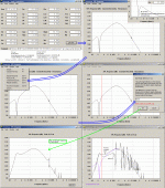
Why don't you post the input HR screen addressing the two pictures in posting # 207 I scrutinized to be reflecting a very misaligned design?
This could save you if I've done severe mistakes when comparing your Unhorn to my closed resp. ported simulations. I would immediately confess If I'm wrong.
b
Hello Bjorno 🙂
My post was not intended to insult you in any way. But some of the things that are so elementary concerning speaker design and implementation needed to be posted. (only in my opinion of course)
Yes this is a misaligned enclosure. I think misaligned in order to achieve a greater efficiency over a narrower bandwidth. It will require filtering but this is a sub-woofer design not a mid-woofer design. It will not work as a low to mid-woofer design. As you have correctly pointed out there is to much peaking above 80 hz.
Your application of Hornresp to simulate the two MCM drivers is interesting. I used Winisd to do this quickly as I am fairly proficient with it. I could have used BassBox Pro as well but they give almost the same results. It could be that I did not try enough different alignments as your results are much better.
But I am a bit confused as to what you are saving me from making a mistake in? The original box worked in the environment it was designed for at the level of efficiency simulated by Hornresp. You correctly pointed out and I agree the original unhorn box did not follow the schematic specs completely. It was a quick cut and try. But it did work and work well. The peak in the response is a function of the mouth being a bit to large and the measurement location in the car. With the redesign it is actually smoother in response. So it works as designed and as measured.
The second enclosure will be put to the same test. I'm going to test it carefully. I have my software up and running on my computer and it will be measured more comprehensively this time. I hope you will be encouraged by this. And yes I will measure it outside on a ground plane measurement at 10 meters. (that is weather permitting) At least I will be able to figure out what is going on a bit better.
This is a big experiment. If it works great. If it does not work then at least something has been learned from it. At least from my end of things. I can pop out a tapped horn design quite quickly. A unique design takes a little longer. One that performs well and is smaller in size will take longer yet. But if it works or not I have still grown in experience. I think that is the whole point of this thread.
Mark
An externally hosted image should be here but it was not working when we last tested it.
Now I'm really puzzled
Bjorno how did you get the graphs you posted?
I ran the exact same numbers and I get very different results.
Did I input something incorrectly? Because this does not look like the curves that you have displayed.
Mark
Bjorno how did you get the graphs you posted?
I ran the exact same numbers and I get very different results.
An externally hosted image should be here but it was not working when we last tested it.
Did I input something incorrectly? Because this does not look like the curves that you have displayed.
Mark
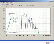
Hi Mark, Maybe this picture will help you?
b
PS: More to come ,I'm quite busy for the moment. 🙂
Attachments
Ok self explanitory. No port contribution in my graph. But this is still at a much higher power input and into 1/8th space. Two drivers surface area becomes the limiting factor to be sure. But the enclosure still contributes at least 6 db of gain. That is a four times improvement.
Mark
P.S.
Not reading the manual gets you every time !
Mark
P.S.
Not reading the manual gets you every time !
..Ok self explanitory. No port contribution in my graph. But this is still at a much higher power input and into 1/8th space..
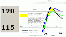
Mark,Are you insisting that by using 1/8th Space or any other angle would make a difference to my arguments?
Two drivers surface area becomes the limiting factor to be sure. But the enclosure still contributes at least 6 db of gain. That is a four times improvement.
Mark
As over-flooded in this whole tread is:You're still writing redundant or non-substantiated numbers with no reference at all and draw your own odd conclusions that have no value at all especially when directing an thread answer towards me. Don't you understand that this can be taken as attempts to 'Trolling for Newbies'?
P.S.
Not reading the manual gets you every time !
On this we seem to agree, at least. 🙂
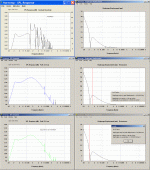
Here comes the last pictures using your own HR input data showing that
your driver specs. doesn't improve your case at all but the opposite.
b
Attachments
Last edited:
Hi there, just read the whole thread.
I also like clean low bass, with a flat response, and in the many boxes I've built I've had good luck with 4th order bandpasses(for a flat response). Anyways my setup is a little more insane, I might be one of those morons that listens to rap.
Anyways 114dB with 2 7" drivers and what 22wrms? That's pretty good, but I think you can do better. You would likely get a similar response from those 2 drivers sealed(as the inner most one contributes virtually nothing to the output). Maybe try it out and see!
If you feel like making some sawdust, perhaps try mounting your two subs parallel to each other, making the box necessarily twice as wide. Obviously you will need to shift some other parameters. Maybe make the path length longer so you can dig down lower...
But I'm glad to see another Canadian playing around with tapped horns 😀 I wish my one would fit in a car....but it's about 14cuft external...It's 1/4 wave length is about 19.5Hz 😀
I am too lazy to read this entire thread, perhaps someone can answer my question:
Has this design been measured?
In my experience, the simulations of tapped horns are not accurate above the first octave or two. Sorry David, but these things measure a lot flatter in the real world than the sims would indicate.
I see a lot of people obsessing over a few centimeters here, and a few centimeters there, when it really just boils down to a few things:
- Tapped horns aren't anything magical, and Hoffman's Iron Law still applies. If you think that you're going to get 10db more efficiency than a ported box, you will be disappointed.
- The biggest challenge is getting the first notch above the passband. Solve that and the rest is fairly easy.
- Because there's no rear chamber, these things WILL unload if the length is too short. Because of that, I personally prefer to trade some efficiency for a much longer length, to keep excursion under control
- The simulations REALLY fly out the window when you use more than one woofer
- I've created a model in Akabak for dual and quad woofer tapped horns, which shows that multiple woofers smooth the response of a tapped horn significantly
- Multiple woofers also reduce the height and depth of the impedance peaks, which makes them use less amplifier power (IE, the dips in impedance is broader and shallower)
- Stop spending so much time in front of Horn Response and make some sawdust
I am too lazy to read this entire thread, perhaps someone can answer my question:
Has this design been measured?
[*]Stop spending so much time in front of Horn Response and make some sawdust
[/list]
Hello Master Bateman! Good to see you here. I surely do admire your work in the unity horn for your car thread.
To answer your question check out the following links:
See posts 16-25,32,41,43
http://www.diyaudio.com/forums/showpost.php?p=1856932&postcount=16
http://www.diyaudio.com/forums/showpost.php?p=1859291&postcount=25
http://www.diyaudio.com/forums/showpost.php?p=1859960&postcount=32
http://www.diyaudio.com/forums/showpost.php?p=1861375&postcount=43
These are the simulations and measurements of the little brother of said UNHORN2. SPL in a car spec'ed out at what Hornresp said it would. Impedance peaks were relatively close due to my fast and loose horn fold. The frequency response was pretty damn close as measured and posted in post #55. A critique by a couple of young lads in post #82,83.
http://www.diyaudio.com/forums/showpost.php?p=1867485&postcount=82
Review in post #102
(http://www.diyaudio.com/forums/showpost.php?p=1875476&postcount=102)
As well as a better location in the car for the meter and a frequency response that was within +/- 2db from 35 to 100hz.
What is being debated ad nauseum right now is the bigger brother that everyone wants. So plenty of sawdust. The new box is designed. The fold is worked out and the parts are cut. I just have to finish the assembly and test the monster.
An externally hosted image should be here but it was not working when we last tested it.
The best answer comes from the barrel of a microphone! YES?
Mark
I want to build one, but I don't think I can get down or past 20 hertz with decent output given the space I have to work with.
Hi Winslow
What kind of space are you talking about? The bigger UNHORN is just over 2 cubic feet.
The little unhorn is less than a cubic foot.
So among a zillion other possible configurations you have two more.
Mark
What kind of space are you talking about? The bigger UNHORN is just over 2 cubic feet.
The little unhorn is less than a cubic foot.
So among a zillion other possible configurations you have two more.
Mark
I just wonder if I could equal or surpass the output of a 15 like say an AE IB15 with a TH in my constraints.
Winslow "I have about 3.5 cubic feet to work with inside my tirewell to work with."
What shape is this space in the tire well? Are we talking a donut hole in the floor tirewell?
And what kind of a 15" driver are we talking about?
If all goes according to simulations and the efficiency is close to real life you can strap on another 6 db for in car response.
This box is not the loudest. Nor the most efficient. It is a best compromise between the two in the smallest size I can come up with. A true front loaded horn will be better and even a tapered quarter wave length horn ala Voight pipe will be more efficient. But they will be a lot bigger.
Mark
It is mostly rectangle. I am not afraid to use an airsaw to make it completely rectangle if I knew it would be worth it.
Worth it in comparison to what?
Amongst all the stuff in this thread is the cold hard facts that for a given radiator surface area you will not get any louder no matter how much power you pour in. A horn of any shape or design is not magical. It simply interfaces with the room it is in with greater efficiency than a direct driver.
If you think of your driver in terms of a downward pressure on a lever as per the illustration you get more work done for the lower illustration for a given input of force. This is a more efficient box design like a horn loaded enclosure. Both illustrations with the same input of power will produce a different result in actual work done. But the lower one will get more work done or move more air in our favor per unit of power input.
All this wonderful efficiency gain comes at the price of box size and construction difficulty. If you take a vented box and pour in enough watts you will get equal SPL most of the time. If you use a truly optimized and reactance anulled front loaded horn you will come out the winner. THe best gain I have seen is 10 db over a normal box be it vented or sealed.
The UNHORN design is neither reactance anulled nor a front loaded horn design. It is 1/2 as efficient. It provides a gain of about 6 to 7db. It drastically lowers the useable bandwidth of a driver as does any horn loading. What any horn loading does is get you a greater sound pressure level with less cone excursion. You also get a more dynamic sounding bass response because you have a greater efficiency. This generally translates into less distortion. I don't know how to explain it properly but horn loaded bass sounds more like your there in a live venue and less like your listening to a recording. I personally think all the complexity is worth it on those points alone.
OK enough ranting. What are the specs of your 15 inch that we are competing with?
Don't forget that two 8 inch drivers do not even equal the surface area of a 12 inch driver. So we need some specs to see what we are up against. Then we can see if it is really worth the effort.
Mark
Amongst all the stuff in this thread is the cold hard facts that for a given radiator surface area you will not get any louder no matter how much power you pour in. A horn of any shape or design is not magical. It simply interfaces with the room it is in with greater efficiency than a direct driver.
An externally hosted image should be here but it was not working when we last tested it.
If you think of your driver in terms of a downward pressure on a lever as per the illustration you get more work done for the lower illustration for a given input of force. This is a more efficient box design like a horn loaded enclosure. Both illustrations with the same input of power will produce a different result in actual work done. But the lower one will get more work done or move more air in our favor per unit of power input.
All this wonderful efficiency gain comes at the price of box size and construction difficulty. If you take a vented box and pour in enough watts you will get equal SPL most of the time. If you use a truly optimized and reactance anulled front loaded horn you will come out the winner. THe best gain I have seen is 10 db over a normal box be it vented or sealed.
The UNHORN design is neither reactance anulled nor a front loaded horn design. It is 1/2 as efficient. It provides a gain of about 6 to 7db. It drastically lowers the useable bandwidth of a driver as does any horn loading. What any horn loading does is get you a greater sound pressure level with less cone excursion. You also get a more dynamic sounding bass response because you have a greater efficiency. This generally translates into less distortion. I don't know how to explain it properly but horn loaded bass sounds more like your there in a live venue and less like your listening to a recording. I personally think all the complexity is worth it on those points alone.
OK enough ranting. What are the specs of your 15 inch that we are competing with?
Don't forget that two 8 inch drivers do not even equal the surface area of a 12 inch driver. So we need some specs to see what we are up against. Then we can see if it is really worth the effort.
Mark
Ok it's sitting behind me!
A bit of time to measure will be needed but I listened for a couple of hours in the car. It really kicks butt. Put the box through it's paces with some serious organ music and some lute and then chamber orchestra. Then tried some stuff with drums of all kinds. The more real taught a drum sounds the cleaner the transient response of a driver/box combination. The drum still has to have kick and impact but not the thud so many sub-woofers reproduce as a poor excuse for a drum.
The measurements will tell something or the other.
Here are the caveats. This box is designed for the MCM 8 inch drivers. It is optimized to the maximum. At a normal wall mounting it will get you 96db/watt. In a corner 102db/watt. With the TRIO8 the SPL response is not as high right off the start as it is a bit less efficient. But the ultimate top end SPL is a bit better with the TRIO8. I didn't have any MCM drivers on hand so I stuffed it with what I had. I consider the TRIO8 A much better driver at any rate.
I will post the plans as soon as I draw them.
Mark
An externally hosted image should be here but it was not working when we last tested it.
An externally hosted image should be here but it was not working when we last tested it.
An externally hosted image should be here but it was not working when we last tested it.
Get you a cutting!
Here is a construction drawing. Full scale with some cleaner lines drawn in.
This is what I used to make it. I drew the folding so many times I lost count. It is not optimal. THe driver placements are pretty darn close to the original design. The mouth is the non optimal part. There is a rise in the response up to 100 hz. But put a 12 to 13 millihenri inductor in series and you get rid of most of that problem. Hornresp tells me that this is 96 db/watt in a wall position. It's to late to do that level of SPL testing tonight. But If things work out tomorrow we will see. It rained like crazy here half of the day.
One thing David McBean should be happy about is that horn response predicted the upper peak in impedance exactly! 48hz 34 ohms. The lower one I can't figure out but I will try and measure it with some other means than the Woofer Tester. I'm tired and the Woofer Tester is so easy.
Mark
Here is a construction drawing. Full scale with some cleaner lines drawn in.
An externally hosted image should be here but it was not working when we last tested it.
This is what I used to make it. I drew the folding so many times I lost count. It is not optimal. THe driver placements are pretty darn close to the original design. The mouth is the non optimal part. There is a rise in the response up to 100 hz. But put a 12 to 13 millihenri inductor in series and you get rid of most of that problem. Hornresp tells me that this is 96 db/watt in a wall position. It's to late to do that level of SPL testing tonight. But If things work out tomorrow we will see. It rained like crazy here half of the day.
One thing David McBean should be happy about is that horn response predicted the upper peak in impedance exactly! 48hz 34 ohms. The lower one I can't figure out but I will try and measure it with some other means than the Woofer Tester. I'm tired and the Woofer Tester is so easy.
Mark
One thing David McBean should be happy about is that horn response predicted the upper peak in impedance exactly! 48hz 34 ohms.
Hi Mark,
You are right - hearing things like that does make me very happy indeed 🙂.
It sounds almost too good to be true, though - in this case it's probably due more to "dumb luck" than to anything else...
Kind regards,
David
I have to admit, I've been interested in this project (and others like it) but in this case I'm a little confused as to what the point is.
If I'm reading your measurements correctly, we're talking about a subwoofer cabinet of 30.75" x 26" x ~10". That's gotta be just South of 4 cubes.
Honestly, with the sub taking that much space in a rectangular form factor, why not just use something like a Maelstrom-X firing up? It might be a little (but not much) less efficient in the midbass bass, but power's easy and cheap to get today. And output potential at all frequencies will be higher.
- Status
- Not open for further replies.
- Home
- Loudspeakers
- Subwoofers
- Tapped Horn For Car


