Hi permo,
Post #80: "...have not cut any wood yet...".
Usually, on a layout like this, you would start by drawing the location of the dividers on the inside of a side board. For that method the side board would be the full size of the outside of the box (depth and height). All the internals would then be the same width.
But, you may want to consider another possibility, namely attaching the top and bottom (and the 2 internal dividers) to reduced size side plates, and then mounting front and rear boards against that from the outside. The tops and bottoms would be the same width as the front and rear. Together with the two internal dividers that would be by far stable enough, and you can attach the front and rear boards with screws to the sides and top/bottoms, and to whatever braces you add on the inside. It's easy to change the dimensions, the side board height = total box height minus 1.44" (2 x 0.720"), and the depth = total box depth minus 1.44". The front and rear would be total box height x total box width, and you just cut out the front opening to fit. If you are worried that the sides of the front opening are getting a little too weak you can add a little thickness there, and increase the height to give you the same S4 (or, you brake up the front board into two pieces, and fill in the gaps on the side board with wood strips).
I doubt that it is necessary to double up on any of the wood pieces, even though it cannot hurt as long as you make up for any reduced air path volume.
Anyway, just another way to look at it.
Regards,
Last edited:
Hi permo,
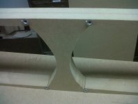
I had a little extra time and scratched around on the drawing a little more with respect to implementing side access lids for an inverted driver. As bjorno suggested, it would be easiest to just double up on the driver baffle, and, to provide additional wood to screw into, I also doubled up on the bottom section of the vertical divider. The outside dimensions change a bit (when you make the box deeper the duct length increases, so you have to reduce the height a little, etc.). With this change the S1 to S2 section now has its normal taper back, and S1 is as in bjorno's original design.
Again, you only need the side access lids (one on each side) if you go for the Push-Pull driver arrangement.
Regards,
Attachments
Last edited:
Hi permo,
I had a little extra time and scratched around on the drawing a little more with respect to implementing side access lids for an inverted driver. As bjorno suggested, it would be easiest to just double up on the driver baffle, and, to provide additional wood to screw into, I also doubled up on the bottom section of the vertical divider. The outside dimensions change a bit (when you make the box deeper the duct length increases, so you have to reduce the height a little, etc.). With this change the S1 to S2 section now has its normal taper back, and S1 is as in bjorno's original design.
Again, you only need the side access lids (one on each side) if you go for the Push-Pull driver arrangement.
Regards,
Man you are good. I think I might have to modify my cutsheet now and do the double baffle. I like that idea.
Hi permo,
I noticed I made a mistake when plotting the drawing to pdf. I got the wrong portion of the drawing (by now there are a bunch of boxes in it). So I'll call this one the "finished" version Rev_02b.
Please, note the depth change to 23.614" outside dimension, and the change of S1. I also added a few additional dimensions.
I hope you'll go through this in detail to catch any other errors. Would be nice to end up with a finished drawing of sorts.
Regards,
Attachments
I REALLY, love the new design. The 1.5" thick MDF baffle is a fantastic idea. I am starting to get really anxious, but I am having a hard time deciding what wood to use in addition to MDF. Baltic Birch is so dang spendy....but I would hate to cut corners on this project.
To make a long story short, all the internal baffles, dividers and braces will be 3/4 inch MDF for sure. Its the outside panels which I will be sanding and staining that I am most concerned with...the top, bottom, front, rear, and sides.
I am still leaning towards both drivers just firing forward, but I still like the idea of the extra 22" on the vertical divider right behind the drivers.
I have all my screws, 1 1/2 inch sheetrock, wood glue, liquid nails, foam weatherstripping for removable panels, terminal cup...etc..etc.. Just need to take the plunge on wood.
Cut Sheet
One 51 5/16" X 10 1/16" (Back removable)
One 41 31/32" X 10 1/16" (removeable top front, above slot)
One 4 11/16" X 10 1/16" (Bottom Front Below Slot)
Two 22 3/16" X 10 1/16" (Top and Bottom)
Two 49 7/8" X 22 3/16" (sides)
One 22" X 8 5/8" (vertical divider brace)
One 42 31/32" X 8 5/8" (vertical divider long)
two 44 3/32" X 8 5/8" (double slanted divider)
Top and Bottom sits on top of the sides and behind the front and rear
Last edited:
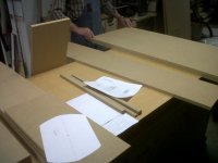
I chose 3/4 inch MDF. The material was cut today. I bought two full 97 x 49 inch boards.
The double thick baffle and horizontal divider are currently under a hydraulic press with veneer glue in between the layers being sandwiched.
I will begin construction tomorrow and I will post pictures as I put it together. I am going to go with the dual forward facing configuration with removable top front hatch (above the slot)
This is going to be an awesome subwoofer.
The only issue right now is I can't find any documentation regarding the size of the cutout.
Last edited:
Hi permo,
The size of the slot @ S4 is 4.672"H x 8.625"W, from the area in Hornresp: S4=260cm^2 (40.3in^2).
I'd make the bottom piece of the front baffle removable too. Make sure you can get to the mounting screws, and get the speaker in and out easily, there is very little room in the width.
Regards,
The size of the slot @ S4 is 4.672"H x 8.625"W, from the area in Hornresp: S4=260cm^2 (40.3in^2).
I'd make the bottom piece of the front baffle removable too. Make sure you can get to the mounting screws, and get the speaker in and out easily, there is very little room in the width.
Regards,
Hi permo,
The size of the slot @ S4 is 4.672"H x 8.625"W, from the area in Hornresp: S4=260cm^2 (40.3in^2).
I'd make the bottom piece of the front baffle removable too. Make sure you can get to the mounting screws, and get the speaker in and out easily, there is very little room in the width.
Regards,
I have that part. I just couldn't find a template for the sub cutouts. I was able to get a document from T and B and make a general template with trial and error yesterday. We should be good to go.
What do you think would be better?
1. rectangle slot with removable top and bottom front panels
2. Single removable front panel with circular opening?
Once again, I can't thank you eneough for your AMAZING work/help on this.
Hi permo,
For a first try I would go with the round port / single front panel. Pictures? 🙂
Regards.
For a first try I would go with the round port / single front panel. Pictures? 🙂
Regards.
Hi permo,
For a first try I would go with the round port / single front panel. Pictures? 🙂
Regards.
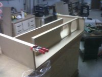
I will post pics tonight for sure. Right now I just have a pile of cut up wood and some boards under presses. Tonight, We will be fitting things together, gluing and clamping. The only board I plan on using screws on is the removable front panel. The entire enclosure, without the front will be wood glued then put under a large press to cure/dry. I will then caulk the seems, add bracing and prepare the front.
Is it still a 7.163" diameter port with the center 7.005 inches from the bottom of the enclosure?
Would routing the edge to smooth the port out cause any issues by reducing the volume a little?
Last edited:
Hi permo,
Yes, the port location and diameter have not changed. Sounds like you have a nice woodworking setup. Are you using braids to hold the boards in place prior to clamping?
Regards,
Yes, the port location and diameter have not changed. Sounds like you have a nice woodworking setup. Are you using braids to hold the boards in place prior to clamping?
Regards,
Hi permo,
Yes, the port location and diameter have not changed. Sounds like you have a nice woodworking setup.
Regards,
I wish it was mine. I have a retired chemical engineer/perfectionist friend with a massive workshop in his basement and two more (including a machine shop) on his property.
The boards are cut accurately within 1/128th of an inch, and we will be mitering the bottom edge of the slanted board at the exact angle for the design.
I will post pics of the project tonight. Hoping to get everything braced, glued and under the press tonight, excluding the front. That will be last.
P.S. It is becoming apparent that this speaker will not be easily transported. It is going to be HEAVY.
Hi permo,
You need to provide some access to the S1/S2 section to be able to change the stuffing. The stuffing is a vital part of bjorno's design.
Regards,
You need to provide some access to the S1/S2 section to be able to change the stuffing. The stuffing is a vital part of bjorno's design.
Regards,
Hi permo,
You need to provide some access to the S1/S2 section to be able to change the stuffing. The stuffing is a vital part of bjorno's design.
Regards,
That was my mistate, the rear is also entirely removable. Just like the front.
Hi permo,
Talking about mistakes, I went over the drawing one more time, and found an error in the length of the long vertical divider board (now: 42.752"). I don't think it matters, but it should ideally be a little shorter than in the original drawing. I also added the dimension for the duct cross-section below the long divider board (1=7.121). See attached drawing.
Regards,
Attachments
Last edited:
Hi permo,
Talking about mistakes, I went over the drawing one more time, and found an error in the length of the long vertical divider board (now: 42.752"). I don't think it matters, but it should ideally be a little shorter than in the original drawing. I also added the dimension for the duct cross-section below the long divider board (1=7.121). See attached drawing.
Regards,
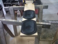
Hey, no big deal. I made it the other way, but I can sand down the panel once everything drys. Tomorow we will mount the drivers and put the removable panels on. Also cut the circular vent hole.
Attachments
- Status
- Not open for further replies.
- Home
- Loudspeakers
- Subwoofers
- Tang Band Tang Band W8Q-1071F 8 X 12 box reccomendation