AFAIK Marcus has tested a T106-2 core compared to a 1D23A-150M filter and the results are more or less the same.
Marcus please correct me if I'm wrong.
BR, Toni
is 1D23A-150M get hot / warm ?
The layout suits both. 1D23A-150M or a T106-2 with 33 turns of 1.0CuL.
Both are equally well suited. Resulting THD and IMD almost identical.
A minor advantage of the T106-2:
It has much more headroom versus saturation and costs a few cents less.
But also the 1D23A is suited for 2R operation, so in case of
the 40V version LiteAmp the decision is mostly a matter of personal taste.
Only if you are heading for an overall low profile, the T106-2 is preferable, because then the PCB allows to place E-caps with a larger diameter and lower height. ==> Option to fit into a 1unit casing.
... a really nice amplifier.
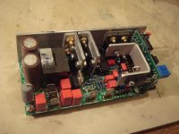
Marcus was so nice to send me some preliminary LiteAmp part kits so I was able to do some "Beta" testing.
Running the LiteAmp bridged at +/- 31V supply was a big success. Without any optimizations on components and cabling the THD+N out of the box is really impressive:
0.0051% 1kHz@1W@8R
0.0026% 1kHz@10W@8R
0.0056% 1kHz@50W@8R
0.024% 1kHz@100W@8R
0.025% 1kHz@150W@8R
SNR better as 110 db (A-weighted with 20kHz prefilter, referenced to 150W output)
goes to Chocoholic for this nice and powerful amplifier.
BR, Toni
Choco
Is the aim to sell this commercially, I think I would buy some them if the price is right, even just the boards ?
seem to me 1D23-150M better looking in that beautiful PCB and also far more easier than buy T106-2 and winding the coil.
Is the aim to sell this commercially....?
Not commercially.
But I will provide variations of different Key Component Sets for the components which I think are critical for the success.
Like a group buy, no charge for my efforts.
The intension is to enable a very high quality DIY classD amplifier
which many people can afford.
My previous projects clearly were to complicated and to expensive
for offering a group buy.
The LiteAmp fills this gap and by restricting my group buy activity
to the key components, I hope that I can handle the logistics.
I intend to offer the KCS as soon as also the gain board is ready.
The main board without gain board won't make happy most people,
because it needs a huge input signal of 8Vp for full power.
When ready, I will put posting(s) describing the sets and costs,
also showing the BOM+buidling instructions+PDFs of the PCB.
So everybody can see from the very beginning which things you will need to organize on your own and which parts you can get from me.
I intend to have the collection of orders public, but of course the personal data by PM.
Until that I have to ask for patience, currently I have to many tasks running at the same time.
Last but not least many thanks to our 'beta-tester' for his valuable feedback.
His comments greatly helped to remove misleading pit falls in my building instructions.
@ ChocoHolic, may We know the impedance for 8Vp ?
its bring more fun to me i just imagine a hybrid amp SRPP 6922 with ClassD
can I do that ?
its bring more fun to me i just imagine a hybrid amp SRPP 6922 with ClassD
can I do that ?
Not commercially.
But I will provide variations of different Key Component Sets for the components which I think are critical for the success.
Like a group buy, no charge for my efforts.
The intension is to enable a very high quality DIY classD amplifier
which many people can afford.
My previous projects clearly were to complicated and to expensive
for offering a group buy.
The LiteAmp fills this gap and by restricting my group buy activity
to the key components, I hope that I can handle the logistics.
I intend to offer the KCS as soon as also the gain board is ready.
The main board without gain board won't make happy most people,
because it needs a huge input signal of 8Vp for full power.
When ready, I will put posting(s) describing the sets and costs,
also showing the BOM+buidling instructions+PDFs of the PCB.
So everybody can see from the very beginning which things you will need to organize on your own and which parts you can get from me.
I intend to have the collection of orders public, but of course the personal data by PM.
Until that I have to ask for patience, currently I have to many tasks running at the same time.
Last but not least many thanks to our 'beta-tester' for his valuable feedback.
His comments greatly helped to remove misleading pit falls in my building instructions.
🙂
Such a generous guy, thanks mate, create a donation page I will be happy to donate then.
Until that I have to ask for patience, currently I have to many tasks running at the same time.
take your time no pressure. good luck.
...
Last but not least many thanks to our 'beta-tester' for his valuable feedback.
His comments greatly helped to remove misleading pit falls in my building instructions.
You are welcome! And there wasn't really a pit fall as the SystemD LiteAmp modules worked out of the box!
More measurements and pictures will follow...
BR, Toni
@ ChocoHolic, may We know the impedance for 8Vp ?
its bring more fun to me i just imagine a hybrid amp SRPP 6922 with ClassD
can I do that ?
Do you mean a tube frontend?
Googled one SRPP using 6922 tube. Seems to have a 10k output impedance. IMHO this is too high for driving the LiteAmp
BR, Toni
@ ChocoHolic, may We know the impedance for 8Vp ?
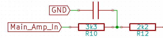
Attached the input section. The cap towards GND is 1nF.
In simplified view the node on the right hand side of R12 can be
counted as a virtual GND.
Despite the low input impedance, it is possible to drive it from higher impedances. The LiteAmp remains stable and well behaving.
But of course - when driving from higher impedances - you need to consider the voltage divider formed by your high output impedance and the input impedance of the LiteAmp.
Attachments
Last edited:
That's highly welcome.More measurements and pictures will follow...
Your mechanical work is so much better than mine!
Do you mean a tube frontend?
Googled one SRPP using 6922 tube. Seems to have a 10k output impedance. IMHO this is too high for driving the LiteAmp
BR, Toni
No problem always a way out for a problem.
by the way very good looking amp.
Attached the input section. The cap towards GND is 1nF.
In simplified view the node on the right hand side of R12 can be
counted as a virtual GND.
Despite the low input impedance, it is possible to drive it from higher impedances. The LiteAmp remains stable and well behaving.
But of course - when driving from higher impedances - you need to consider the voltage divider formed by your high output impedance and the input impedance of the LiteAmp.
I see it I think I can find the solution for that Just let me know when the liteamp release to public.
Hi guys,
I'm reading this thread a third time now, as I'm fascinated in the technical background and Marcus' ideas and implementations, and also the technical explenations, which I see not as a kind of teacher-behavior, but as a noob (which I am) a possibility to learn.
Although I have still not finished the 2k amps I'm curious for next results, pics and finally the boards, as I plan to finish my actual project hopefully next week.
Marcus, wish you further good ideas and a lot of time for your hobby 😉
Stammheim
Although I have still not finished the 2k amps I'm curious for next results, pics and finally the boards, as I plan to finish my actual project hopefully next week.
😎
In case of any hazzle just give me call.

And of course I would love to see pics of your 2kW build in the 2kW thread.

Some more measurements ...
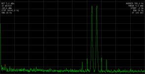
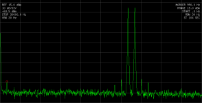
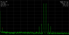
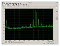
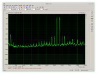
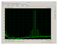
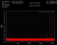
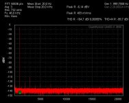
Have had some time to do some more measurements of a single SystemD LiteAmp. Attached some IMD measurements made with 2 different measurement chains.
All measurements done with +/- 31V regulated PS.
Measurement chain A:
IMHO a very nice implementation of IRS2092 with very low distortion figures especially in the critical 0.1 - 10W range.
BR, Toni
Have had some time to do some more measurements of a single SystemD LiteAmp. Attached some IMD measurements made with 2 different measurement chains.
All measurements done with +/- 31V regulated PS.
Measurement chain A:
- Hameg HMF2525 Arbitrary Function Generator with homebrew 19/20kHz IMD wave.
- HP Spectrum Analyser 3585A
- Software "ARTA" as IMD 19/20k Generator and Analyzer
- Soundcard Asus Xonar STX (headphone output set to 300-600R)
1kHz@1W@8R 0.0040%
6kHz@1W@8R 0.015%
1kHz@16W@8R 0.0048%
6kHz@16W@8R 0.045%
1kHz@32W@8R 0.019%
6kHz@32W@8R 0.24%
SNR in reference to 1kHz@50W@8R 107dB (bw. 20k)6kHz@1W@8R 0.015%
1kHz@16W@8R 0.0048%
6kHz@16W@8R 0.045%
1kHz@32W@8R 0.019%
6kHz@32W@8R 0.24%
IMHO a very nice implementation of IRS2092 with very low distortion figures especially in the critical 0.1 - 10W range.
BR, Toni
Attachments
-
 liteamp_imd_1w_astx.png6 KB · Views: 1,272
 -
 liteamp_imd_10w_astx.png6.6 KB · Views: 1,243
 -
 liteamp_imd_20w_astx.png6.4 KB · Views: 1,233
 -
 liteamp_imd_20w_astx_xonar_stx.png37.8 KB · Views: 216
 -
 liteamp_imd_10w_astx_xonar_stx.png37.5 KB · Views: 234
 -
 liteamp_imd_1w_astx_xonar_stx.png36.8 KB · Views: 1,224
Last edited:
@ ASTX,
can you made a measurement max voltage before clipping.
THD+N 48W@8R at or near clipping with +/- 31V power supply voltage:
1kHz: 0.9%
6kHz: 1.3%
BR, Toni
Looking good. Interesting figures and many thanks for measuring and posting them.
Just a small post to let know that I'm still here, waiting for its release 🙂
Just a small post to let know that I'm still here, waiting for its release 🙂
Gain Board Builders Package
Here is the full builders package of the gain board with limiter.
The differential amp behaves as blameless like one can expect from modern OP amps.
Touching my measurement limits for THD & IMD. Step response has a sloping time of 300ns and is free of overshoot.
Most liekly this board will not the bottleneck, but of course you can also experiment with
OP amps different from the OPA2134.
Two PCB are possible:
1) Dated: 21.11.2014
2) Dated:17.10.2014
Dated 17.10.2014 is tested, but has Silk Screen Errors.
Marking of +12V & -12V interchanged. ==> Popular knowledge: Plus is Minus and Red is Blue....
Polarity marking of C110 interchanged. ==> Correction: Minus of real component must point towards LED!
Cathode marking of D104 wrong. ==> Correction: Cathode of real component must point towards Q2 !
P.S.
The BOM contains not just the BOM, but also hints and instructions!
Enjoy your build
Markus
Attachments
-
 Gainboard_IMD_Out6V86p_Load3k3.JPG58 KB · Views: 354
 -
 Gainboard_THD_Out6V86p_Load3k3.JPG59.5 KB · Views: 726
 -
 LiteAmpComplete.jpg41.5 KB · Views: 737
 -
LiteAmpGainBoardBOM20141121.pdf256.6 KB · Views: 505
-
LiteAmpGainBoardBack-brd.pdf38.7 KB · Views: 387
-
LiteAmpGainBoardFront-brd.pdf71.2 KB · Views: 412
-
LiteAmp(Gain)_Gerber_20141017.zip58.3 KB · Views: 253
-
LiteAmp(Gain)_Gerber_20141121.zip58.3 KB · Views: 298
-
LiteGain_40V.pdf96.1 KB · Views: 690
-
 50kHz_Rectangle.jpg58.7 KB · Views: 425
- Home
- Amplifiers
- Class D
- SystemD LiteAmp