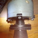
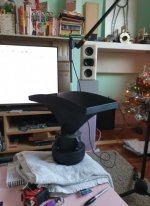
Your horns are set-up for the small bolt pattern JBL uses for most of their 1.5" horns. It will probably get a bit better with the horn firmly attached and aligned.
Rob 🙂
Rob 🙂
Hard to tell really.
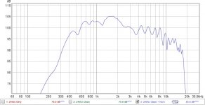
I assume the drop @3 K shouldn't be so steep, then again it's a guess with measurements without baffle and semi fixed couplings of the driver to the horn.
Is the drop also there without the horn?
From recollection:
It should measure almost flat (6 to 9 dB total) from 600/800 Hz to around 10KHz, if measured from a foot/30 cm or so and without horn. Forgive me if I'm off on the top end by 2 K or so.
Either way: it should not have drops like those at 3KHz already.
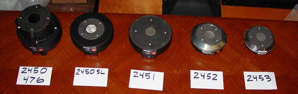
The 2450SL version is just like this one regarding physical matching of length/size/shape/place of screw holes etc to the horn. No difference, except a cover over the now exposed shiny steel part, to get the same foward facing level. Man I know that's not what I meant. Rephrase:
SL versions won't help you get the horn and driver easier attached. You'd have to sort that out: maybe there's a space between the driver and the horn (doubt it).
I can take a look at my work tomorrow if I can spot any physical things in between driver and horn if you want, but those are equipped with slightly different drivers (476mg I suppose).
They could be based on these exact same 2450 core (tulip), dunno..
I assume the drop @3 K shouldn't be so steep, then again it's a guess with measurements without baffle and semi fixed couplings of the driver to the horn.
Is the drop also there without the horn?
From recollection:
It should measure almost flat (6 to 9 dB total) from 600/800 Hz to around 10KHz, if measured from a foot/30 cm or so and without horn. Forgive me if I'm off on the top end by 2 K or so.
Either way: it should not have drops like those at 3KHz already.
The 2450SL version is just like this one regarding physical matching of length/size/shape/place of screw holes etc to the horn. No difference, except a cover over the now exposed shiny steel part, to get the same foward facing level. Man I know that's not what I meant. Rephrase:
SL versions won't help you get the horn and driver easier attached. You'd have to sort that out: maybe there's a space between the driver and the horn (doubt it).
I can take a look at my work tomorrow if I can spot any physical things in between driver and horn if you want, but those are equipped with slightly different drivers (476mg I suppose).
They could be based on these exact same 2450 core (tulip), dunno..
<<<<<SNIP>>>>>>>>>>>
I have no idea how I'd attached the two together...
Use Woofer Clamps clamped to the 4 corners of the horn's driver mounting flange ( turned to be closest to the existing snout holes ).
Here's how I attach an ancient RCA 1.4" driver to a horn.

An externally hosted image should be here but it was not working when we last tested it.
Called "McGivering"
Lucky for you there are quite a few JBLers willing to hand-hold ( as long as the project doesn't get too boring ).
🙂
Attachments
Thanks EarlK, I needed this for a modified 2450 and 2384 🙂
No need to use some souble sided adhesive or anything?
No need to use some souble sided adhesive or anything?
Thanks EarlK, I needed this for a modified 2450 and 2384 🙂
No need to use some souble sided adhesive or anything?
The previously pictured 1.4" to 2" adapter ( NLA from Selenium ) has a very thin ( crushable ) foam face on each end.
There's no slipping what-so-ever.
Therefore, I would recommend making a gasket of some sort ( auto supply houses sell all sorts of gasketing supplies for the DIYer ).
( FYI, Eminence sells a nice affordable 1.4" to 2" adapter these days .)
An externally hosted image should be here but it was not working when we last tested it.
> though it doesn't have any gaskets on it.🙂
Last edited:
Use Woofer Clamps clamped to the 4 corners of the horn's driver mounting flange ( turned to be closest to the existing snout holes ).
I wouldn't do that, The threads only extend the thickness of the bottom plate if you try to use longer screws you will pull the plate off the magnets and kill the driver.
Rob🙂
I wouldn't do that, The threads only extend the thickness of the bottom plate if you try to use longer screws you will pull the plate off the magnets and kill the driver.
Rob🙂
Good Point Rob!
In the example I displayed above, the 1/4-20 holes disappear into the hollow magnetic structure of that RCA driver ( so there's no concern about driving into + cracking open the magnet ).
How thick is that plate ( not many threads I suppose )?
Threaded studs could be used on the outer perimeter holes ( so that the tightening force is only the nut turning down onto the already seated stud ).
Like this;
From This thread at LHF
🙂
Last edited:
Thanks, great advice!
The 2384 is a 1.5" horn though (and the snout off the 2450), but same rules apply.
Feeling like a McGyver already😀
The 2384 is a 1.5" horn though (and the snout off the 2450), but same rules apply.
Feeling like a McGyver already😀
Thanks for the replies, people!
I forgot to add this image earlier.
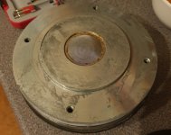
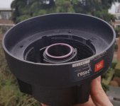
It appears that the SL has a flush/flat mesh whereas the J has a domed mesh which protrudes into the horn when I took this measurement. Perhaps a shim is needed. I can experiment with thick card, perhaps!
I forgot to add this image earlier.
It appears that the SL has a flush/flat mesh whereas the J has a domed mesh which protrudes into the horn when I took this measurement. Perhaps a shim is needed. I can experiment with thick card, perhaps!
Attachments
Good Point Rob!
How thick is that plate ( not many threads I suppose )?
🙂
9.8 mm, approximately 8 threads.
Yet, I'm guessing this strict depth also applies to the standard SL version since the same holes are used.
I can take a look at my work tomorrow if I can spot any physical things in between driver and horn if you want, but those are equipped with slightly different drivers (476mg I suppose).
They could be based on these exact same 2450 core (tulip), dunno..
Yes please! I speculate that the SL casing provides a very shall throat beginning!
Subwoof ( Mike ) has answered a lot of those sort of questions over at LHF !
IOW, I don't keep close track about those details > since I usually know where to find the answer .
🙂
IOW, I don't keep close track about those details > since I usually know where to find the answer .
🙂
Last edited:
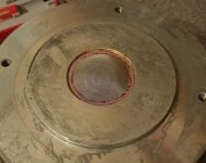
This gives you a good understanding on how the driver goes together. This equivalent to a 2451 and has the bolt pattern for your horn. No it's flush, thickness of the bug screen, and the if you look closely the raised circle is the flush mount without the 1/4 20 tapped holes.
476Mg
Rob 🙂
476Mg
Rob 🙂
Last edited:
This gives you a good understanding on how the driver goes together. This equivalent to a 2451 and has the bolt pattern for your horn. No it's flush, thickness of the bug screen, and the if you look closely the raised circle is the flush mount without the 1/4 20 tapped holes.
476Mg
Rob 🙂
There is an enlarged space around the screen for the throat to connect from the 2450J snout, tho. The screen is domed on this model but after thinking it does protrude in to the snouth throat original attached.
However, I remembered I did a measurement out of sheer curiosity the other day to see what the response looked like with the 1.5" horn rested on the 2" aperture:
There is a dip at 1.25k that is consistent with the drivers with snout but no horn as well and shows up on both. Although the craziness above 3K is due to the reflections and differing sizes of aperture it does show the dip sharp reduction in response.
Attachments
For the woofers, how about four FaitalPro 8PR200 in series parallel? According to my sims, In a sealed box of only 31ltrs it should give you an F3 (-3db) of about 80hz and an F6 of about 74hz. Efficiency at 1mtr 2.83v is about 94db.
They should be able to go incredibly loud too!
EDIT: That was with the 16ohm version of the driver.
They should be able to go incredibly loud too!
EDIT: That was with the 16ohm version of the driver.
Last edited:
For the woofers, how about four FaitalPro 8PR200 in series parallel? According to my sims, In a sealed box of only 31ltrs it should give you an F3 (-3db) of about 80hz and an F6 of about 74hz. Efficiency at 1mtr 2.83v is about 94db.
They should be able to go incredibly loud too!
EDIT: That was with the 16ohm version of the driver.
Hello!
I just looked back at my first post and realised I got my model numbers wrong! The 8PR200 is what I have been thinking of to use 2 per side NOT 8FE200!

Hello!
I just looked back at my first post and realised I got my model numbers wrong! The 8PR200 is what I have been thinking of to use 2 per side NOT 8FE200!
2 x 16ohm drivers in parallel should work fine in about 15ltr sealed.
I've been looking at this FR all day at work and what I initially thought was breakup (combing from 8-9k upwards) is actually what I think to be a disruption caused by the mismatch of the horn to the silver plate. The original "snout" pressed down in to the recess around the mesh forming a seal and began the 1.5" throat. The problem is, I think, that there is now a void where this throat once was.
Here is a diagram marked with pink dots to indicate what I'm talking about.
I realised this after I noticed the similar pattern from the FR of the horn on top of the 2" aperture and the horn on top of the mesh.
How should I fill this gap? I was thinking maybe foam gasket strips on the horn flange that butts up. I dont want to put anything on the mesh that is adhesive for fear of pulling the mesh up later down the line.
I've marked all parts I'm talking about with light pink highlighter.
Annoyingly I wont get a chance to test this theory until the weekend but I will be able to clamp the CD and horn together and do some on and off axis measurements!
Attachments


- Home
- Loudspeakers
- Multi-Way
- System Based Around JBL H9800 Horn