the wide variance in qts will likely have a severe effect on response. low qts drivers have a narrow peak in port output, higher qts value drivers have a wider peak in port output.
not to mention the otther effects that varied qts will have on the horn response itself.
not to mention the otther effects that varied qts will have on the horn response itself.
the wide variance in qts will likely have a severe effect on response. low qts drivers have a narrow peak in port output, higher qts value drivers have a wider peak in port output.
not to mention the otther effects that varied qts will have on the horn response itself.
Understood! Thanks for the reply!
Art.
I got my hands on a pair of DH1A's.
What would you thoughts be on adapting the SyntripP for those CD's
I got my hands on a pair of DH1A's.
What would you thoughts be on adapting the SyntripP for those CD's
If you remove the 1.4" to 2" adapter the DH1A becomes a DH1AMT, it will fit with no modification of the SynTripP plans. The hex screws holding on the adapter "snout" are coated with Loctite, heating the screws makes it easier to remove them. I broke one of the screws off when removing a DH1A snout before realizing heating loosens Loctite.Art.
I got my hands on a pair of DH1A's.
What would you thoughts be on adapting the SyntripP for those CD's
Cabinet weight will increase from 34 to about 52 pounds using the DH1 rather than a neo driver.
Last edited:
JBL 2447H 1.5" Titanium Horn Driver 8 Ohm
Do you think a JBL 2447J would be a good candidate for Syntripp?
I can get it for a fraction of the cost of a Celestion CDX14-3050
Thanks
Do you think a JBL 2447J would be a good candidate for Syntripp?
I can get it for a fraction of the cost of a Celestion CDX14-3050
Thanks
Yes, and the saved money can be put towards the Truextent beryllium diaphragms for which the 2446 and later JBL drivers are very good base due to their phase coherent phase plugs. If it's pro use, then keep the original JBL 'phragms 😀.
Thanks Legis, I'm just thinking of gutting out a JBL SR4732A and making a syntripp out of it.
Nice system you have there, liking that red synergy and tap horn you have posted. How low does your synergy horn go?
I have a baby unity horn painted red just like it 🙂

Nice system you have there, liking that red synergy and tap horn you have posted. How low does your synergy horn go?
An externally hosted image should be here but it was not working when we last tested it.
I have a baby unity horn painted red just like it 🙂
Last edited:
Thanks JSS🙂. Cute red horns.
They go pretty low, quite like sealed normal speakers perhaps. Mathematically the horn loading stops at ~95-90Hz, but they go lower than that in a typical room.
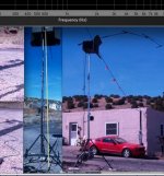
Here's listening spot measurement with and without the THs:
They go pretty low, quite like sealed normal speakers perhaps. Mathematically the horn loading stops at ~95-90Hz, but they go lower than that in a typical room.
Here's listening spot measurement with and without the THs:
An externally hosted image should be here but it was not working when we last tested it.
They have been in various positions. I like them best when they are only ambient tweeters without direct radiation to listening spot. This way they do not mess with the point source feeling at all. Thus they (2 per ch) have been sitting on the synergy's compression drivers illuminating the ceiling. 🙂
An externally hosted image should be here but it was not working when we last tested it.
Martin,
The speaker stands are Global Truss ST-132.
The microphone stand and two booms are K&M.
Art
The speaker stands are Global Truss ST-132.
The microphone stand and two booms are K&M.
Art
The SynTripP is a lot more challenging build than the Keystone Sub, don't stumble, be careful, and good luck !
I have a lot more time available now. I'm going to build 2 more KS for a total of 4 and run 2 of these for mains. I'm sure I will be here with plenty of questions.
Still on the radar
I still have this build on my radar.
I have been toying with the 3D model, which I propose to turn into cut sheets.
The model helps get the cuts, angles and sizing right, so as to correctly interpret the 2D hand drawings.
I have the B&C mid drivers...two of them at least.
I still have this build on my radar.
I have been toying with the 3D model, which I propose to turn into cut sheets.
The model helps get the cuts, angles and sizing right, so as to correctly interpret the 2D hand drawings.
I have the B&C mid drivers...two of them at least.
ART:
On the top-down drawing, it appears there are TWO different configurations for the BR port walls.
I assume the walls in red that a parallel are to accommodate for the pole insert.
Is this correct?
Is one configuration more optimal that the other?
I am probably going to mount mine horizontally and use two per side, as that works well on our mobile vehicle.
In which case I dont need a stand mount....so I am wondering if the angled port walls should go top and bottom?
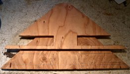
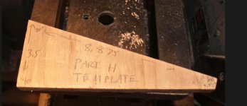
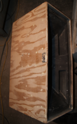
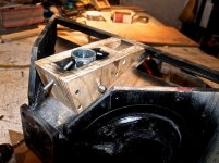
The drawing in post #41 shows the ports in red as built, the angled port walls would have interfered with the tilt assembly and would not have given the desired Fb (82Hz).
The pictures below may help you understand the port configuration. If you are not using the tilt assembly (you will want it for other applications...) just use four part "H".
Art
The pictures below may help you understand the port configuration. If you are not using the tilt assembly (you will want it for other applications...) just use four part "H".
Art
Attachments
- Home
- Loudspeakers
- Multi-Way
- SynTripP: 2-way 2-part Virtual Single Point Source Horn