We have decided to go with a horn similar to the one that is being made out of a Klipsch K402 on the Klipsch Forums. It is a 2 way Synergy type horn, but much bigger than I planned on doing for a 1st attempt. This is what we have so far.
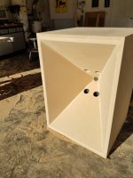
Basic cabinet...


Rear shot of sides mocked up...

Front shot of sides mocked up...

Side panels with ports cut...

Measurements for ports...

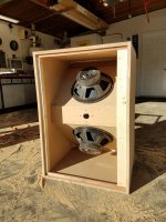
Rear shot of cabinet with woofers installed...

Front shot of horn (still need to trim the horn down to the cabinet size)...

Hopefully next weekend we will be able to get the top, and bottom of the horn constructed. We also will be doing a secondary horn flare which will extend beyond the cabinet (at a different angle than our current extension...which needs to be cut flush with the cabinet front).
Basic cabinet...


Rear shot of sides mocked up...

Front shot of sides mocked up...

Side panels with ports cut...

Measurements for ports...

Rear shot of cabinet with woofers installed...

Front shot of horn (still need to trim the horn down to the cabinet size)...

Hopefully next weekend we will be able to get the top, and bottom of the horn constructed. We also will be doing a secondary horn flare which will extend beyond the cabinet (at a different angle than our current extension...which needs to be cut flush with the cabinet front).
Last edited:
Where are your midranges? 🙁
Copy the Danley formula:
1) compression driver with 1" exit
2) midranges that are 4" in diameter
3) woofers that are 8-12" in diameter
Note that the midranges are the most critical element here. There are dozens of compression drivers that will work, and dozens of woofers that will work. There are literally a handful of midranges that are suitable, and none of them exceed 8" in diameter. (And that's pushing it.)
We are not running a 3 way Synergy horn, but a 2 way Synergy horn. We are using a 2" exit compression driver with a 15" woofer. My current setup is a JBL 2360A horn crossing over at 400Hz to my bass bins. The Synergy style horn we are building is to eliminate the JBL 2360A horn, and the bass bins. I am modeling it somewhat from this horn.
For the horn mouth transition... If i get modeling clay, what kind of tools do you need for modeling? I am going to be doing a transition from a circle to a rectangle. Is modeling clay paintable?
tia,
Ron
tia,
Ron

I've found from my experience the easiest way to make the mouth transition is to design the horn so that it terminates in an undersized square. e.g. for a 1" exit CD have the horn end in a flat square with height/width of .707". Then take a 1" bit and drill through. Finally, take a file or sandpaper and sand away wood until the transition is beautifully smooth.
It may be too late for you to take this approach, but I really like it because all you have to do is remove wood. No messy putties or epoxies to deal with.
It may be too late for you to take this approach, but I really like it because all you have to do is remove wood. No messy putties or epoxies to deal with.
I've found from my experience the easiest way to make the mouth transition is to design the horn so that it terminates in an undersized square. e.g. for a 1" exit CD have the horn end in a flat square with height/width of .707". Then take a 1" bit and drill through. Finally, take a file or sandpaper and sand away wood until the transition is beautifully smooth.
It may be too late for you to take this approach, but I really like it because all you have to do is remove wood. No messy putties or epoxies to deal with.
Yeah, we had planned on a 2" exit point but our calculations were off when we made our woofer ports, and we didn't find out until it was too late. We might still be able to put a wooden block in though and file it out for a nice transition...thanks for the idea. 🙂
More progress pics...
Questions:
1: If I make a flare extension...how do I determine the angle of the flare, and the depth of the flare? By depth I mean, the amount the flare will extend beyond the cabinet. I was thinking of 6" - 12", and i had heard 135 degrees would be the angle, but I am not sure. If we make a flare extension it would be removable as it would decrease the weight, and size for moving them into the room.
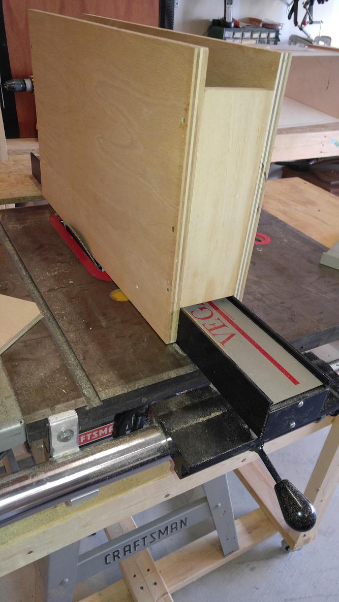
2: Is there a safer way to cut the angle other than angling the table saw blade and running the wood through on edge vs flat on the table saw?
Questions:
1: If I make a flare extension...how do I determine the angle of the flare, and the depth of the flare? By depth I mean, the amount the flare will extend beyond the cabinet. I was thinking of 6" - 12", and i had heard 135 degrees would be the angle, but I am not sure. If we make a flare extension it would be removable as it would decrease the weight, and size for moving them into the room.
2: Is there a safer way to cut the angle other than angling the table saw blade and running the wood through on edge vs flat on the table saw?
Attachments

According to Keele, the angle (as measured from the axis) of the 2nd flare should be 1.5times the angle of the main flare. Starts between 0.65 and 0.75 of the total length. It would make your horn considerably larger, if that matters (good for lower directivity control, not so good for fitting into a room).
I figure on my spreadsheet how to always have the angles cut with the board flat on the table saw surface. Looks like you did the mouth edge different, so I don't think you have much of a choice unless you can find a tapered router bit of just the right taper.
I figure on my spreadsheet how to always have the angles cut with the board flat on the table saw surface. Looks like you did the mouth edge different, so I don't think you have much of a choice unless you can find a tapered router bit of just the right taper.
Last edited:
I've wondered that myself. I have seen some jigs on Youtube, but haven't ever built one. It seems sometimes building the jig is more time consuming than the speakers.2: Is there a safer way to cut the angle other than angling the table saw blade and running the wood through on edge vs flat on the table saw?
Look like you made a lot of dust. 🙂
I've built a vertical jig - just two pieces of plywood that embrace the fence on my table saw - and never considered it more or less of a safety issue than any other use of the table saw. Yes the blade is exposed but your hands are going to be busy pushing the flare along the jig so you don't have to worry about them straying into the blade.
Attachments

2: Is there a safer way to cut the angle other than angling the table saw blade and running the wood through on edge vs flat on the table saw?
https://drive.google.com/drive/folders/0BxsgqQl3NiLuTmxxdzFZaGtneGM
This was a setup posted by Mark Kravchenko. The blade is buried in the jig so it should be pretty safe.
https://drive.google.com/drive/folders/0BxsgqQl3NiLuTmxxdzFZaGtneGM
This was a setup posted by Mark Kravchenko. The blade is buried in the jig so it should be pretty safe.
Sure, you could put the jig on the other side of the blade for safety's sake. Just add a sacrificial layer. The main thing though is to make sure the jig is stable. If you don't have a wide fence, you might want to add an outrigger.
3+ years later?... I have managed to acquire 4 K402 horns, and we have the ports cut out in each horn. Currently the front motherboards are being made from 2 layers of MDF glued together for a 1 1/2" thickness. The sides, top, bottom and rear will all be 1 1/2" thick too. We are using EV DH1Adrivers, and Kappa 15c woofers. We are going to try out them cabinetless, and full cabinet. They will be mounted vertically with the woofers on the top and bottom of the horn when viewed from the front (not sure if this makes sense, but they horn will be the same way as the ones Chris made on Klipsch Forums...except we are standing g the horns on their ends in a cabinet). Wht fronts, and the cabinets will all be veneered in Mahagony. Speakon connectors will be used on the cabinets. Hopefully they will be ready to tune in the next couple of weeks.I will post up pics as we progress more.


Today I picked up all the pieces for the front 3 horns, plus a spare....minus veneer and cabinets. Starting tomorrow I will start on the backbone frame, and then decide on the cabinet shape, and design. Once we test one without a cabinet, and another with a cabinet... I will then get them veneered with my Mahogany veneer. Hopefully they will be to the listening/tuning stage sometime next week.


We now are in the process of tuning all 3 with no cabinet, and I must say they sound damn good. I do not know how long it will be fore I can make a cabinet due to the Corona virus though.
Here is an update... I decided to change the support for the horn, and make the frame curved to where it is 9" narrower in the rear. In actuality this is what I wanted to integrate into the design all along. This is pretty much how the boxless version will look other than cleaning up the holes, and painting the frame...the front baffle will eventually be veneered in Mahagony. The Center channel will be the 1st speaker of the 3 that will try out a cabinet. I am making all the frames as close as I can to being identical, so the cabinet can be moved to the left or right for testing fairly easily.

Great project !!!
Are you hoping to leave them boxless?
Where do you cross to the CD?
Also curious if you will maybe use a sub(s)?
I've been very interested in the k-402 as a synergy horn, largely because of Chris A's build and other happy k-402 campers in general. Seems like a great horn.
I was going to copy a k-402 clone made into a synergy as posted by Oohms on the Klipsch forums, but I got ambitious and decided to go for an even bigger horn.
Just beginning to ring out a pair that measure 122x74 cm at the mouth,
straight conical first 2/3, then quasi-tractrix last 1/3.
It's crazy the number of small details that go into a synergy, huh?
- Home
- Loudspeakers
- Multi-Way
- Synergy DIY