If you don't have excel try Open Office Calc this works well and can load and save xls (excel files)
https://www.openoffice.org/product/calc.html
The closest thing to what you describe as a working design is this Synergy style speaker in a Klipsch Horn, not sure if you have seen it.
http://www.diyaudio.com/forums/multi-way/285108-different-horn.html
Asking any one driver to cover a very large range of frequencies brings about the potential for modulation distortion, i.e. large bass movements affecting smaller movements from the upper range and that is mentioned by cask05 in the thread above.
Also the #1 picture you posted is based on a tractrix Horn profile so it will be more directional, this can help to avoid floor and ceiling reflections but is very different to a conical horn.
Thanks, I found my Excel copy. I have talked with Chris about his setup, and I am trying to get my feet wet with a 2' x 2' horn for now, and once i have it up and running I will work on the Synergy woofers for it. If all turns out as well as I anticipate I will move to a bigger version of some sort.
I have loaded the Synergy calc, but now i am lost as to what to input. I have also loaded up HornResp, but I am lost on what settings go where. I have never built a speaker before that I was designing...so I am really lost here. Could someone please help we walk through this one this time?
For this experiment I am trying to do a 60 degree horn that is 2' x 2' x 2' (using 1/2" plywood). I will use my EV DH1A as my driver, and once we get measurements of it...the plan is then to figure out what drivers to use, and where to place the ports for them.
For this experiment I am trying to do a 60 degree horn that is 2' x 2' x 2' (using 1/2" plywood). I will use my EV DH1A as my driver, and once we get measurements of it...the plan is then to figure out what drivers to use, and where to place the ports for them.
Look at the pdf for very detailed instructions --
http://libinst.com/SynergyCalc/Synergy%20Calc%20V5.pdf
(sorry about the Gnumeric problem, I didn't know they stopped doing Windows...)
http://libinst.com/SynergyCalc/Synergy%20Calc%20V5.pdf
(sorry about the Gnumeric problem, I didn't know they stopped doing Windows...)
OK, this is what I have so far...
[URL=http://s1065.photobucket.com/user/ellisr63/media/calc%201st%20pic_zpsmemq1lce.png.html]
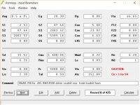
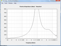
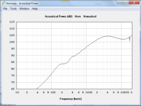
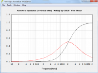
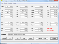
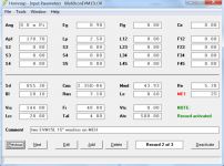
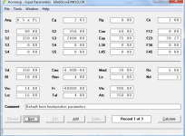
and for HornResp...
[URL=http://s1065.photobucket.com/user/ellisr63/media/hornResp1_zpsiqpqcexj.png.html]
Where can I find the info needed for hornresp for the EV DH1A that are needed for Sd, Bl, Cms, Rms, Mmd, Le, and Re?
[URL=http://s1065.photobucket.com/user/ellisr63/media/calc%201st%20pic_zpsmemq1lce.png.html]
An externally hosted image should be here but it was not working when we last tested it.
[/URL]and for HornResp...
[URL=http://s1065.photobucket.com/user/ellisr63/media/hornResp1_zpsiqpqcexj.png.html]
An externally hosted image should be here but it was not working when we last tested it.
[/URL]Where can I find the info needed for hornresp for the EV DH1A that are needed for Sd, Bl, Cms, Rms, Mmd, Le, and Re?
You are going to have trouble finding T/S parameters for almost any compression driver. they are seldom published. I have the attached model params for a BMS4550 that you could start, with beefing up at least the Sd for the EV-I. It probably has a stronger magnet also. But anything that is reasonable is probably good enough to show you if you have your woofer entry holes in a good enough position.
Why a 90x90 horn? 90x90 does indeed make it taller, which gives better vertical pattern control. At the same time that 45 degree vertical half angle is likely to direct sound within the pattern at both the floor and ceiling such that it will bounce back in your face, thus negating the benefit of the better pattern control.
In a Synergy, the 90x90 expands very rapidly forcing you to have the woofer entry holes very close to the apex, so that the mid ports are less than 1/4 wavelength apart at XO and the circumference is less than a wavelength. If you did a 60x60 horn, you could have the ports further down the horn wall which would make mounting your 15" woofers easier.
Attachments
Thanks, I didn't realize a 60 would be better for a Synergy. I have a fully treated room, with first reflection panels on the side walls and ceiling...also the speakers will be on a stage with the ceiling 7' above the stage) (3 of these will be going behind a 15' wide AT screen)...if that makes any difference.
Last edited:
the spreadsheet and HornResponse tips are for the offset drivers (mids or woofs), not for the HF horn at the apex. There are ways now to model the HF at the same time, but the spreadsheet and pdf don`t cover that. As parameters for HF drivers are hard to come by, I just look at the HF data sheet and assume it will behave similarly.
As said, a narrower horn won`t control to as low a frequency. Considering that high frequencies aren`t hard to absorb or control other ways, I'd go for the wider angle myself if there`s a choice. Having good control only down to 2 of 3 kHz isn`t very helpful, IMO.
I would say draw out your room and see what coverage angles you need to hit all the seats and to see where the first reflections go. If your room is well treated then you don't need as much directivity than if it wasn't because the treatments will kill reflections that higher directivity might prevent.
I think a 90x90 horn will be a challenge with a 2" exit CD, especially in terms of HF beaming. The horn walls will indeed be at 90 degree angles but unless you do an exceptional job on the throat, the sound won't fill the entire 90 degrees.
Bigger is always better for LF. A 60 degree horn will have to be deeper/longer than a 90 degree horn to reach the same mouth size and its the mouth size that matters. Its not the horn angle that determines LF coverage but the width or size itself.
That is not to say that 90 degree horns can't be done successfully. Mine is 90x45 and Bwaslo's CoSynes are 90x60.
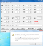
You have an S5 error in your Hornresp screenshot above. Remove the S4 value in the box circled red in the picture below and it will go away, you already have the S4 value included in the other box up and to the right

As nc535 and Bill have said a 90x60 will give you wider horizontal directivity with reduced vertical directivity, 60x60 with the same width will load the mids lower as the horn will be deeper.
It is helpful to use a CAD program or pen and paper to actually draw the horn and where the drivers can be positioned physically as there is no point in making a Hornresp sim that can't actually be built with the drivers you have. Sometimes it is easier to fit the drivers on a 90 degree panel other times 60 works better to try and get the ports towards the corners of the horn and closer towards the centre of the drivers.
Your EV driver will cross low but even with an 800Hz or lower crossover the mid ports will need to be quite close to the apex and awkward to mount with large drivers. Have a look art Art's SynTrip-P thread as that is using 10" inch woofers and a roughly 700 to 800 Hz crossover.
In the sim you have above the mid ports are at 1.5 inches which is not really practical with a 10" driver, as in that Cosyne layout Bill was using 2" mids.
Last edited:
Here is what I have so far... Does this look right? Suggestions?
Here is a link to the SynergyCalc, HornResp file, and images.
Here is a link to the SynergyCalc, HornResp file, and images.
Attachments
-
 HornRespScreen6.png80.5 KB · Views: 94
 -
 HornRespScreen5.png62 KB · Views: 81
 -
 HornRespScreen4.png72.1 KB · Views: 109
 -
 HornRespScreen3.png77.6 KB · Views: 103
 -
 HornRespScreen2.png70.5 KB · Views: 450
 -
 HornRespScreenPar3.png80.7 KB · Views: 463
 -
 HornRespScreenPar2.png77.5 KB · Views: 466
 -
 HornRespScreenPar1.png75.8 KB · Views: 465
 -
 HornRespScreen7.png69.9 KB · Views: 91
Getting that simulation up is a great start!
I see you are modelling horn walls, or at least woofer ports, that are an inch thick. You don't need to do that for rigidity; .5" walls with bracing are probably better. In addition though, the shorter the woofer port length, the better because the needed port area scales with port length. Many of us thin out the area near the port holes - frustrums.
You will be able to see the effect of hole area and length if you do another simulation of the woofers as offset drivers on your horn. Then look at particle velocity and reduce the hole size until the peak velocity at max volume gets too high - like in a bass reflex vent. When I did this, I found that if I halved both the hole area and the port length, the velocity saved the same. If you make the holes too small, you will see the low end response suffer somewhat.
You have Vtc in your ME1 model set to zero. This is the volume of air trapped between the cone and the horn wall. There is probably enough air there to pull down the high end of the woofer below 800 Hz. You need to estimate that volume, then include it in the simulation. Most likely you will need to fashion a wooden plug to take up most of that volume to support a >= 800 Hz XO.
You can also vent the rear chamber of your woofers to bring up the low end. I did this and it looks like your woofers are good for a 40 Hz tune.
Wow...that is great news...thanks for the info! I will work on it some more this week, and then hopefully start cutting wood next week for one sample.
We have modded the horn and begun construction, but now I have a question.
We made the sides of the horn rectangles that are angled inward (front to back) to make a triangle... On the top and bottom triangles is the part we are not sure of. Do the sides of the triangles when you cut get cut at an angle or is the standard straight up cut correct?
I am asking this because our new horns are about 46" wide, 26" deep, 32" high, and I don't want to mess up such a big piece of wood.
tia,
Ron
If you're using my spreadsheet, the top and bottom (i.e. the #2) boards don't need to be angled at their left and right edges, as they don't meet up with anything -- On the sides of #2, you can just cut "straight up" (90 degree) style, and it will work. They are extended to on the basic spreadsheet design to provide room for mounting woofer and mid drivers. The front and back edges of that board need to get angled (angles x and w), though to give a good surface for the tweeter mount piece and to join with the front 2nd flare.
If you don't use a 2nd flare, you'll need to figure the angle (w) to cut the front edge of the #2 boards if you want the edge to be horizontal (parallel with the floor). Take your vertical angle ThetaH and divide by 2 to get the new w angle. Similar change for the #1 boards front angle if no 2nd flare....

Edit again: if you cut the #2 similar to triangles, you won't be able to use the #6 type mounting pieces to hold it all together (you'll have to devise a way to hold all the boards together while glue dries).
Edit yet again: if you want the front edge of the top/bottom (#2) pieces to be perpendicular to the floor (so the horn looks like it has a picture frame around it), make the "w" angle = ThetaH/2+90 degrees instead, and similar for the #1 pieces. Might be a trickier cut (turn panel over when cutting or cut from other side of table saw). NOTE THAT THE OVERALL "E" and "B" DIMENSIONS WILL HAVE TO LONGER THAN THE SPREADSHEET CALCULATES IF YOU DO THIS, SINCE THE ANGLE GOES OUTWARD RATHER THAN INWARD. ALSO THE HEIGHT AND LENGTH OF THE OVERALL HORN WILL BE LARGER THAN CALCULATED AS WELL.
If you want to go for maximally simple, you could just cut the "w" and "y" angles straight-up (90 degrees, not odd angles) too and build with that. The outer edges of the horn won't be aligned with room floor or walls, and the front corners might not meet up. But you could trim the corners with sanding or filing if needed, and you'll have a somewhat framed-looking horn front. That way "E" and "B" can stay as-calculated (though the overall height and width of the horn will increase by a little under 2x the wall thicknesses).
If you don't use a 2nd flare, you'll need to figure the angle (w) to cut the front edge of the #2 boards if you want the edge to be horizontal (parallel with the floor). Take your vertical angle ThetaH and divide by 2 to get the new w angle. Similar change for the #1 boards front angle if no 2nd flare....
Edit again: if you cut the #2 similar to triangles, you won't be able to use the #6 type mounting pieces to hold it all together (you'll have to devise a way to hold all the boards together while glue dries).
Edit yet again: if you want the front edge of the top/bottom (#2) pieces to be perpendicular to the floor (so the horn looks like it has a picture frame around it), make the "w" angle = ThetaH/2+90 degrees instead, and similar for the #1 pieces. Might be a trickier cut (turn panel over when cutting or cut from other side of table saw). NOTE THAT THE OVERALL "E" and "B" DIMENSIONS WILL HAVE TO LONGER THAN THE SPREADSHEET CALCULATES IF YOU DO THIS, SINCE THE ANGLE GOES OUTWARD RATHER THAN INWARD. ALSO THE HEIGHT AND LENGTH OF THE OVERALL HORN WILL BE LARGER THAN CALCULATED AS WELL.
If you want to go for maximally simple, you could just cut the "w" and "y" angles straight-up (90 degrees, not odd angles) too and build with that. The outer edges of the horn won't be aligned with room floor or walls, and the front corners might not meet up. But you could trim the corners with sanding or filing if needed, and you'll have a somewhat framed-looking horn front. That way "E" and "B" can stay as-calculated (though the overall height and width of the horn will increase by a little under 2x the wall thicknesses).
Last edited:
I have 3 JBL 2360A horns with EV DH1A drivers...would my horns work as a Synergy horn (using a 10-15" EV woofer)? Someone told me no, but I have also been told yes. Does anyone know if it will, as I don't want to cut the horn up and find out it won't. I would like to make a 2 way Synergy horn that goes down to around 40Hz or so to mate up with my DTS-10 subs.
I was thinking that if I made a woofer plate for the woofers, and made a slot either on the top/bottom (I think this is the flattest area), I would not need a lot of area for the port. On the sides I would have more space, but it is not as flat as the top/bottom, plus the drivers would firing at each other very close to each other.
Ideas, suggestions?
tia,
Ron
IMHO, this will not work. The midranges are way, way too big.
I've tried a gazillion different midranges on various Synergy horns. (The biggest thread on Unity horns here at diyaudio was started in response to a thread that I was writing at audiogroupforum, way back in 2004.)
Although I've tried a ton, I generally prefer the Celestion that Danley himself uses. Although it's not perfect, I haven't found anything that's measurably better. It Just Works and I can't think of a good reason to use anything else.
- Home
- Loudspeakers
- Multi-Way
- Synergy DIY