Alright, I've been told that you need a lot more distance if you are interested in directivity for low frequencies, at least more than 1 m.I have my speakers on a stool so height is about 1m. I place mic at 0.5m and use FDW gate to ensure no ground or ceiling reflection is shown. I can't get much farther away without ground reflection dip.
I'll do a little more experimenting tonight.
/Anton
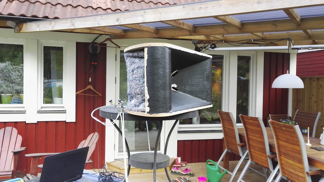
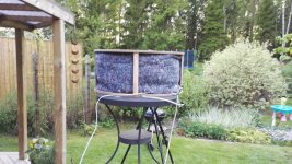
I tried lifting the speaker higher (1.65 m above ground) and measured at 1 m distance. I also did a small change on the backside of the speaker which is now only open straight back with a gap of about 30 cm. The volume is filled with polyfill and the opening is covered with the thick cloth I've used earlier:
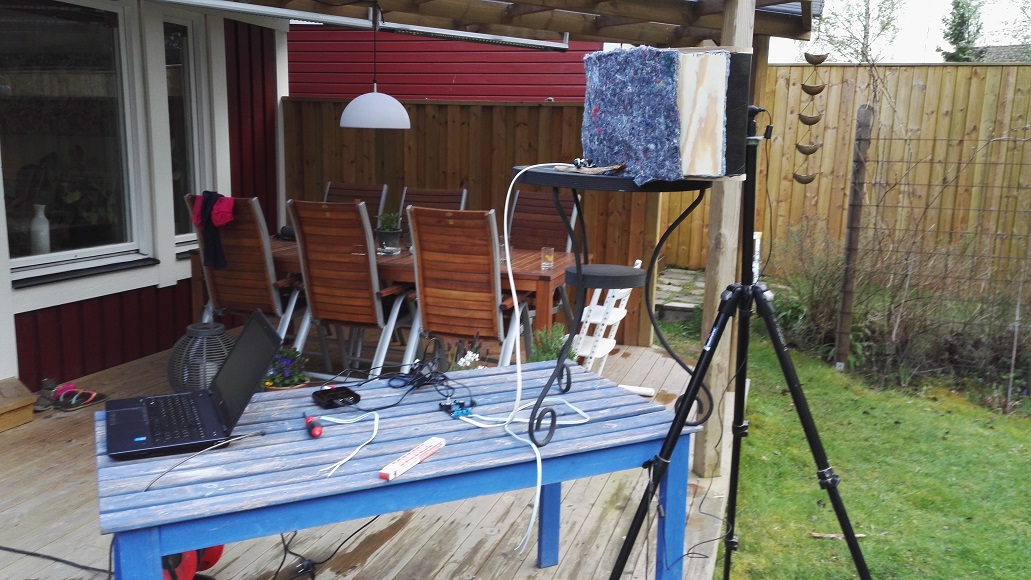
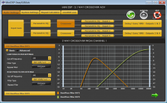
For the woofers I added a first order LP at 100 Hz (to counteract dipole slope) and third order HP at 140 Hz. For the tweeter there is a first order HP at 6 kHz and a LT.

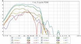
Other than that there is some PEQ on the woofers (one to flatten response around 500 Hz and some above 1 kHz to remove peaks outside the pass band). All measurements with 5 cycle FDW.
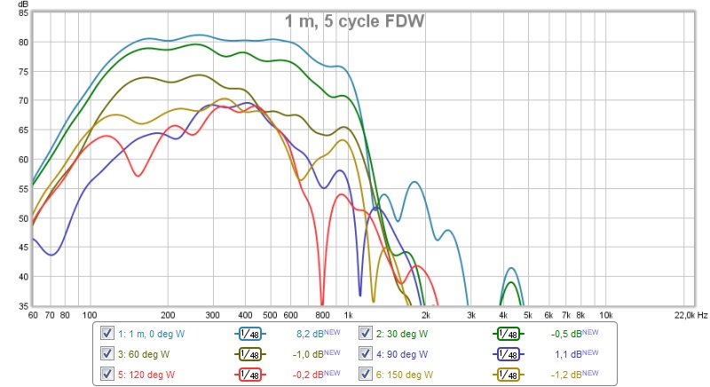
This is the polar response for the woofers:

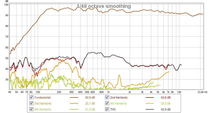
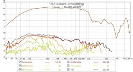
This is what the distortion looks like if I run tweeter and woofers together without any delay:
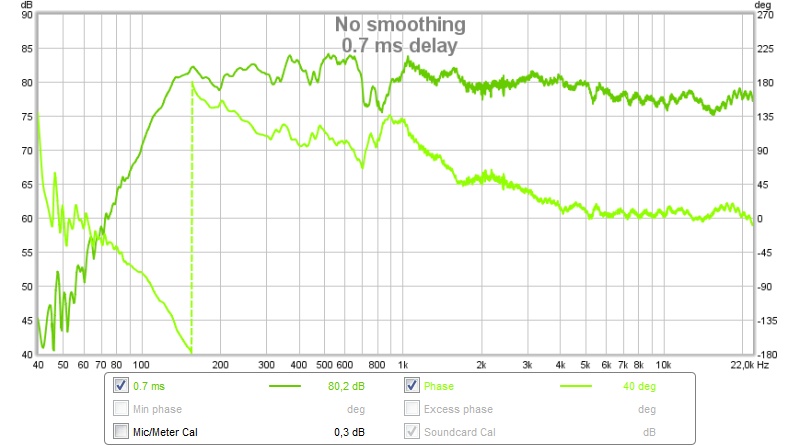
If I add delay (for better transient response) I get this:
I need to work to stretch the output of the woofers to 1 kHz.
I did polars without delay:
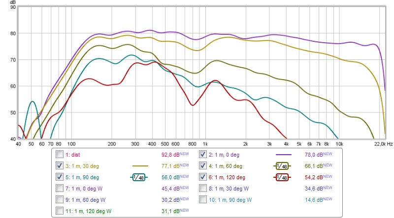
It's primarily the off axis dip between 500 and 1000 Hz that bothers me.
/Anton
For the woofers I added a first order LP at 100 Hz (to counteract dipole slope) and third order HP at 140 Hz. For the tweeter there is a first order HP at 6 kHz and a LT.
Other than that there is some PEQ on the woofers (one to flatten response around 500 Hz and some above 1 kHz to remove peaks outside the pass band). All measurements with 5 cycle FDW.
This is the polar response for the woofers:
This is what the distortion looks like if I run tweeter and woofers together without any delay:
If I add delay (for better transient response) I get this:
I need to work to stretch the output of the woofers to 1 kHz.
I did polars without delay:
It's primarily the off axis dip between 500 and 1000 Hz that bothers me.
/Anton
Attachments


.....I need to work to stretch the output of the woofers to 1 kHz.....
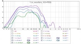
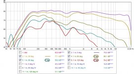
Blue below is from post 176 and there thought you were close to BW4 at 1,2kHz so is it the 100Hz 1st order LP that makes purple curve from todays post have less HF extension, grey curves means and numbers can be read in legend.
Guided by a freeware calculator floor relative level bounce improved from -6,0dB to -10,8dB going from 1,3m height distance 1,5m to 1,65m height distance 1,0m. Calculator plus more available here (Need register) https://www.merlijnvanveen.nl/index.php/en/calculators.
Attachments
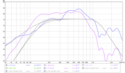
Well, I put a PEQ at the 1000 Hz peak both woofers show at near field measurement:Blue below is from post 176 and there thought you were close to BW4 at 1,2kHz so is it the 100Hz 1st order LP that makes purple curve from todays post have less HF extension, grey curves means and numbers can be read in legend.
Guided by a freeware calculator floor relative level bounce improved from -6,0dB to -10,8dB going from 1,3m height distance 1,5m to 1,65m height distance 1,0m. Calculator plus more available here (Need register) https://www.merlijnvanveen.nl/index.php/en/calculators.
And after that the response falls before 1000 Hz. I didn't like the uneven response around 1000 Hz, hopefully it can be fixed with some volume filler/better shape of BP-holes. There is also some cancelling due to uneven phase behavior above 500 Hz for the two woofers, this is of course due to the difference in routing.
/Anton
I tried reducing difference in pathlength inside the BP chamber by frustumizing the holes towards the center. I've also made the two sides more or less identical (filled some routed groves with wood filler). Now the response reaches ~1 kHz. I made EQ (and HP+LP) at 0.5 m:

This is the response (on axis) at 1 m:

Almost exactly -6 dB at 100 Hz 🙂
The level is maximum all the way (DAC level, miniDSP level, no pot on TPA3116 amplifier), next time I probably should measure with something more powerful.
The peaks at 1.8 and 4.3 kHz should probably be removed.
/Anton
This is the response (on axis) at 1 m:
Almost exactly -6 dB at 100 Hz 🙂
The level is maximum all the way (DAC level, miniDSP level, no pot on TPA3116 amplifier), next time I probably should measure with something more powerful.
The peaks at 1.8 and 4.3 kHz should probably be removed.
/Anton
Attachments

Last edited:
Those are some good looking responses you have there. Good work. Looking forward to the integrated XO.
^^^what he said.
Also, I'm keen to see if the newly frustrumized BP-holes (which I'd love to see a photo of) will have any impact on your previously observed 120deg off-axis dip.
Also, I'm keen to see if the newly frustrumized BP-holes (which I'd love to see a photo of) will have any impact on your previously observed 120deg off-axis dip.
Open back test
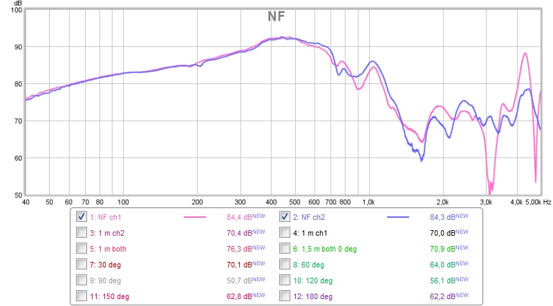
Yesterday I made a test with completely open back. This is the woofer response at 1 m distance, 1.65 m above ground:
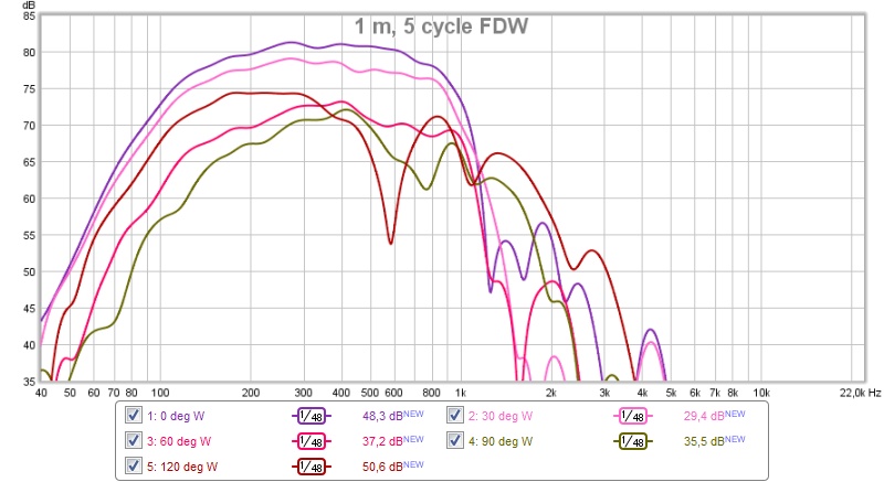
And this is combined with tweeter:
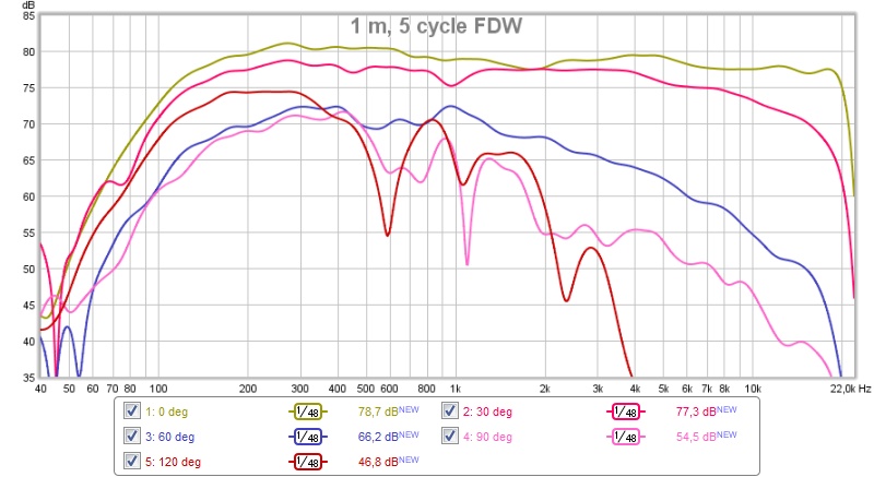
The dip at 500-1000 Hz is gone, but now the level at 120 deg is higher than at 90 and 60 deg. Expected, but not desirable. There is a small dip on axis at 1900 Hz, other than that I'm quite satisfied with the response 0-90 deg. It's a very directional speaker from 110 Hz to 20 kHz.
I'll try adding back panels again, and stuffing.
Edit: The measurements are done with a Harsch type XO.
/Anton
Yesterday I made a test with completely open back. This is the woofer response at 1 m distance, 1.65 m above ground:
And this is combined with tweeter:
The dip at 500-1000 Hz is gone, but now the level at 120 deg is higher than at 90 and 60 deg. Expected, but not desirable. There is a small dip on axis at 1900 Hz, other than that I'm quite satisfied with the response 0-90 deg. It's a very directional speaker from 110 Hz to 20 kHz.
I'll try adding back panels again, and stuffing.
Edit: The measurements are done with a Harsch type XO.
/Anton
Attachments

Last edited:
I remade measurements yesterday with 4 layers of thick felt damping:

Woofer response at 1 m, 1.65 m above ground:
Less output behind the speaker (>90 deg) which was the goal. There is however more separation between 0 and 30 deg than before, which I did not want :/ Disregard the dip at 800 Hz, the EQ was very quick.
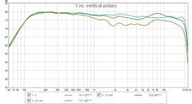
I also made a first vertical polar measurement (0, 10, 20 deg) at 1 m (1.65 m, 1.82 m and 1.99 m above ground):
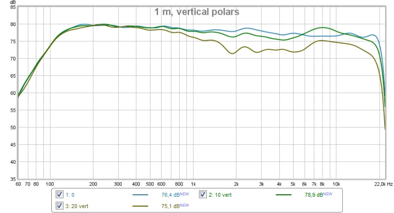
The peak at 10 deg around 8 kHz is a little troubling... Probably due to the 3D-printed part.
Not sure what to make of these measurements and how to proceed.
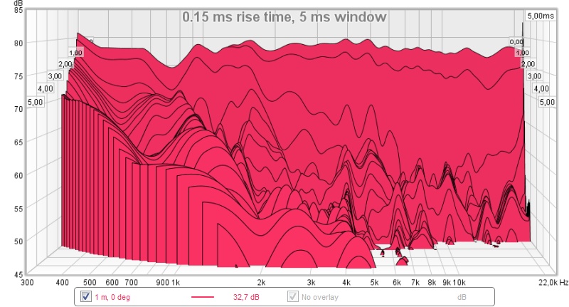
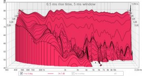
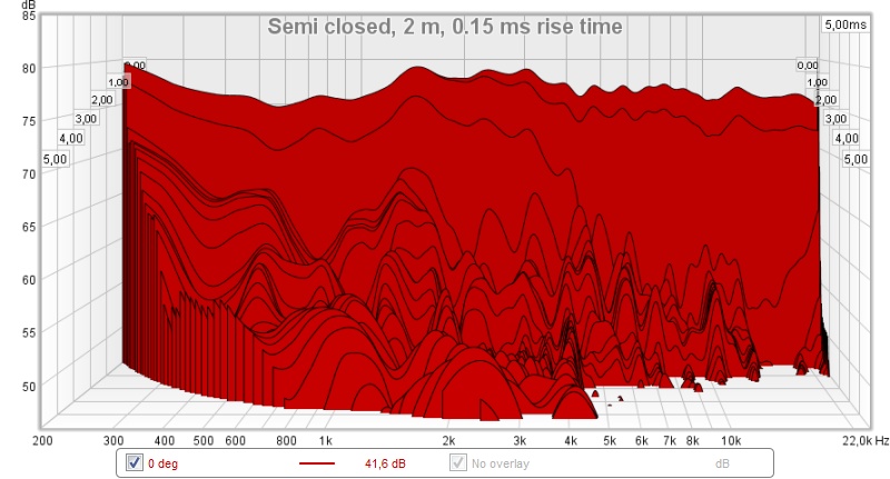
Here are CSD plots with 0.15 and 0.5 ms rise time:

I tried playing music for the first time however, and it sounds really nice. It's impressive how directive the speaker is!
/Anton
Woofer response at 1 m, 1.65 m above ground:
Less output behind the speaker (>90 deg) which was the goal. There is however more separation between 0 and 30 deg than before, which I did not want :/ Disregard the dip at 800 Hz, the EQ was very quick.
I also made a first vertical polar measurement (0, 10, 20 deg) at 1 m (1.65 m, 1.82 m and 1.99 m above ground):
The peak at 10 deg around 8 kHz is a little troubling... Probably due to the 3D-printed part.
Not sure what to make of these measurements and how to proceed.
Here are CSD plots with 0.15 and 0.5 ms rise time:
I tried playing music for the first time however, and it sounds really nice. It's impressive how directive the speaker is!
/Anton
Attachments


Last edited:
.....Not sure what to make of these measurements and how to proceed.....
Think looks great especially CSD's and as i see it ringing tails into CSD in 4kHz area and down is just because of IRR XO and relative high low frq system roll off, so if XO points was linear phase and system had support down to 10-20Hz area those tails would only show up very low dictated by low end amplitude reach.
.....I tried playing music for the first time however, and it sounds really nice. It's impressive how directive the speaker is!.....
Nice enjoy and thanks sharing data and visuals.
Member
Joined 2009
Paid Member
I'm using the UMIK-1 with the corresponding calibration file. I'm hoping that's enough.Are the plots calibrated - what sensitivity do you think is being achieved ?
On sensitivity: No idea, is that really relevant for an all-active system? If I made a passive XO I would burn a lot of energy in the XO and achieve slightly below 90 dB.
/Anton
Don't measure polars too close!
Yesterday I experimented with measuring distance and closing part of the back off.
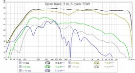
Here are polars with open back measured at 1 m distance:
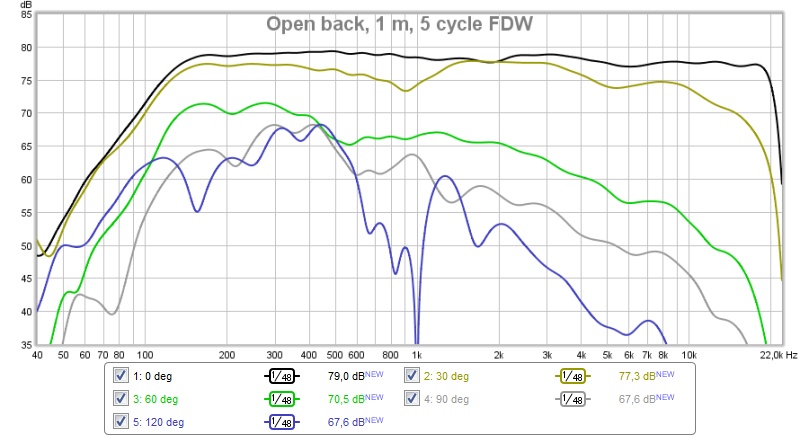
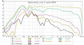
And here is at 2 m:
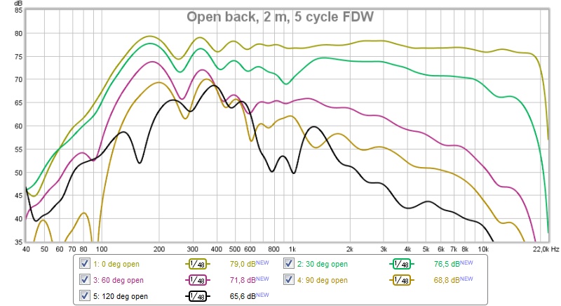
Lesson: Keep a large distance when measuring polars.
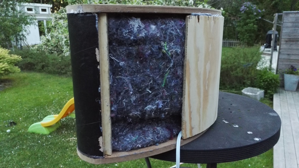
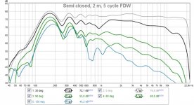
Then I tried adding a panel on the back leaving 18 cm on both sides:
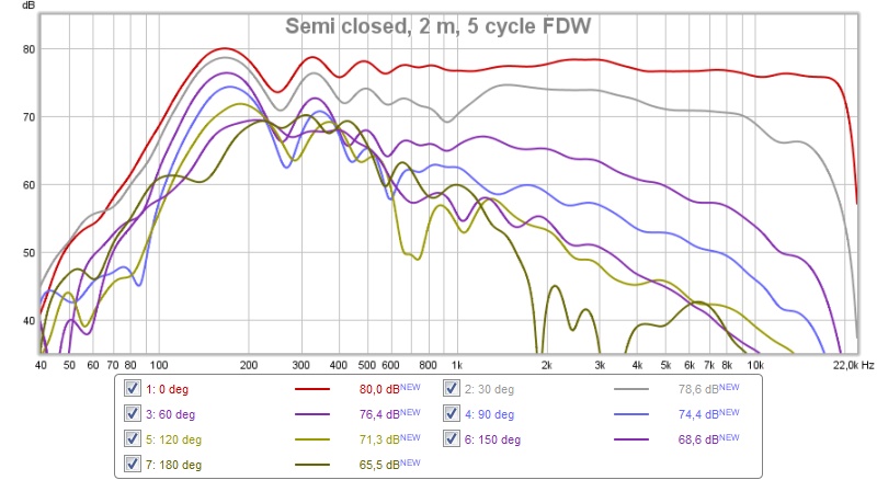
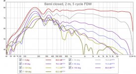
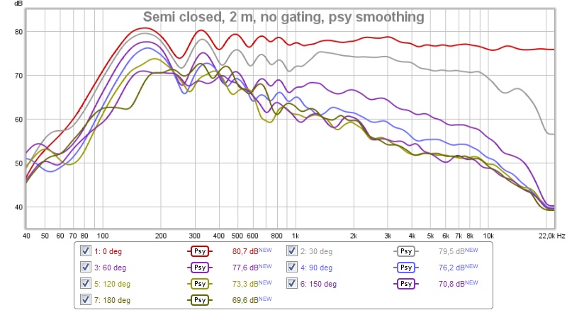
Here is measured polars (0-120°) at 2 m:

And here is all the way to 180°:
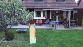
Note that the rear wave measurements are probably affected by the porch, table and wall:

I added another LP for the woofers at 1500 Hz (24 dB/octave) to improve the CSD, here's the result:
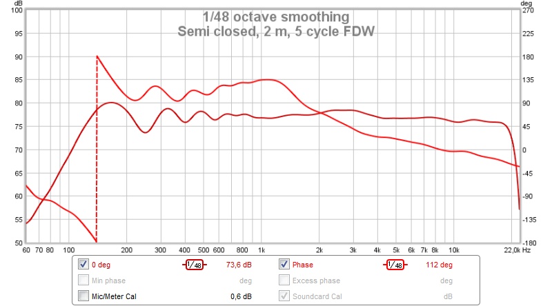
And here is the on-axis response with phase:
/Anton
Yesterday I experimented with measuring distance and closing part of the back off.
Here are polars with open back measured at 1 m distance:
And here is at 2 m:
Lesson: Keep a large distance when measuring polars.
Then I tried adding a panel on the back leaving 18 cm on both sides:
Here is measured polars (0-120°) at 2 m:
And here is all the way to 180°:
Note that the rear wave measurements are probably affected by the porch, table and wall:
I added another LP for the woofers at 1500 Hz (24 dB/octave) to improve the CSD, here's the result:
And here is the on-axis response with phase:
/Anton
Attachments
-
 semi closed, SPL+phase.jpg85.5 KB · Views: 607
 -
 semi closed, 2 m, 5 cycle FDW.jpg108.9 KB · Views: 615
 -
 open back, 2 m, 5 cycle FDW.jpg106.7 KB · Views: 619
 -
 open back, 1 m, 5 cycle FDW.jpg98.3 KB · Views: 625
 -
 IMG_20160530_220903.jpg235.1 KB · Views: 620
 -
 IMG_20160530_220918.jpg322.3 KB · Views: 611
 -
 semi closed, 2 m, 5 cycle FDW, 0-120.jpg102.5 KB · Views: 620
 -
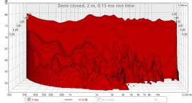 semi closed, CSD 0.15.jpg109.4 KB · Views: 614
The resistive element appears to be having an effect but to my eyes the response still seems dipole in nature with the repeating characteristic dipole peaks and dips (see attached ABC dipole sim). My first guess would be to add delay by adding damping near the vents to further smooth the response. How big are the vents by the way?
Attachments
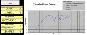
The peaks and dips are ground reflection, compare 1 m and 2 m measurements.The resistive element appears to be having an effect but to my eyes the response still seems dipole in nature with the repeating characteristic dipole peaks and dips (see attached ABC dipole sim). My first guess would be to add delay by adding damping near the vents to further smooth the response. How big are the vents by the way?
The resistive element does indeed have an effect as the resulting polars are close to a cardiod behavior (lowest SPL at 180°), which was the goal.
Each vent is 2 14 mm holes that are drilled so that they touch each other and then made into an oblong shape:

The vents are therefore about 8 cm^2/woofer.
/Anton
Now we're talking!
EDIT: REW had assumed that reflected on-axis peak was the sought off-axis peak (impulse response) which affected a lot of measurements below. Gave weird separation between 60 and higher angles. New figures in later post. /EDIT
I moved the measurements further away from walls and even higher (~1.9 m):

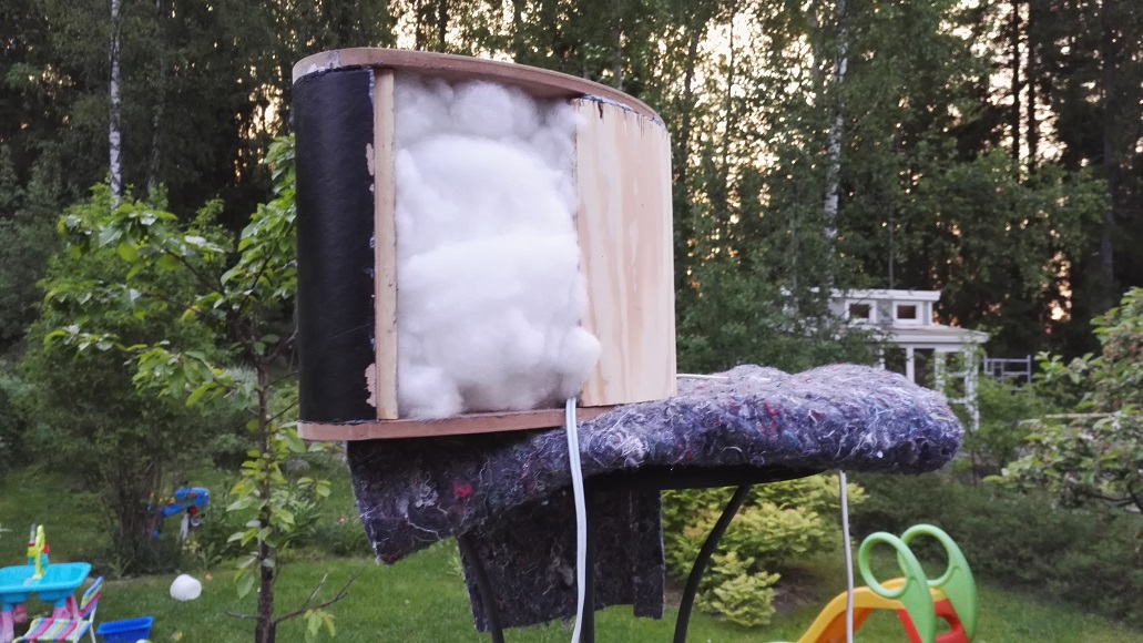
and removed some felt from the backside. With only one layer of felt covering each woofer:
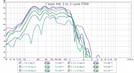
Uh, that's a lot better than earlier measurements. Slightly weird behavior around 1 kHz, woofer response:
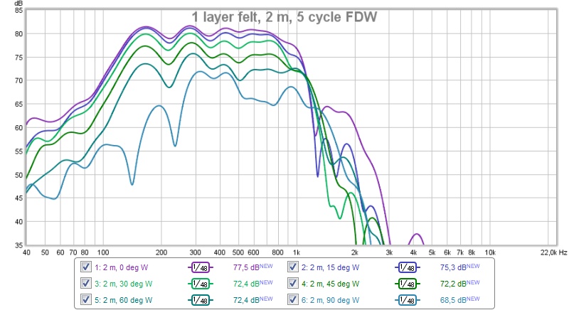
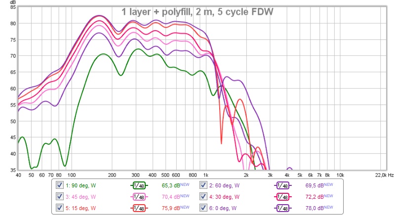
Ah, the output to the sides is a little high around 1 kHz, let's add something that likely absorbs that: polyfill:
Response:
Not bad!
How about with tweeter:
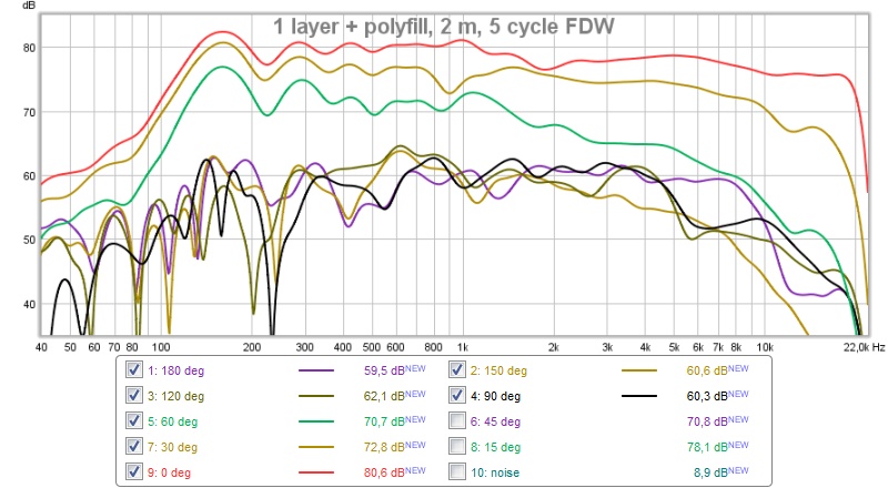
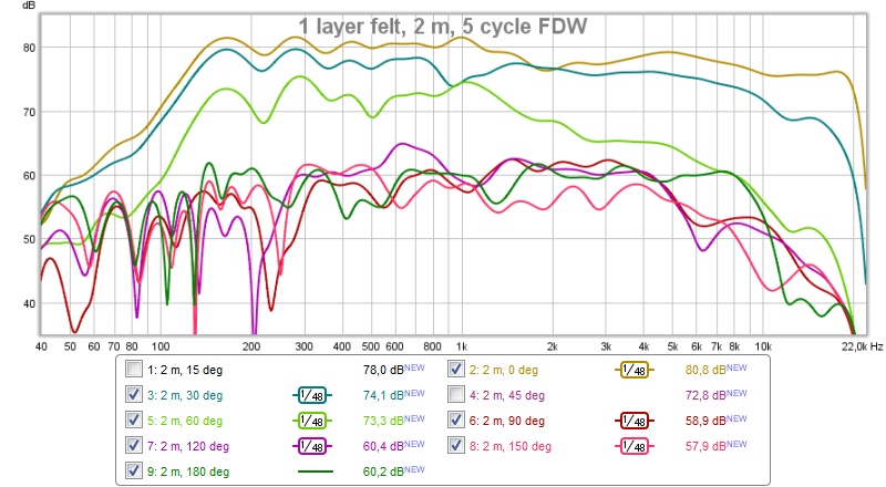
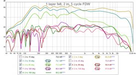
Now we're talking! Here's with 15 and 45 deg angles as well (EQ was done for 15 deg):

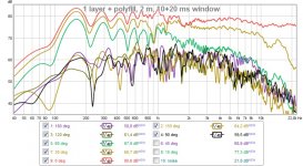
Almost a little suspicious of the FDW, here's with a 30 ms long window (10 ms before and 20 after to avoid wall bounce):

I guess I'm almost done with the improvements on polar response. Maybe add a little more polyfill. The tweeter response was set for a 950 Hz XO, which should be corrected.
I'm psyched! 🙂
/Anton
EDIT: REW had assumed that reflected on-axis peak was the sought off-axis peak (impulse response) which affected a lot of measurements below. Gave weird separation between 60 and higher angles. New figures in later post. /EDIT
I moved the measurements further away from walls and even higher (~1.9 m):
and removed some felt from the backside. With only one layer of felt covering each woofer:
Uh, that's a lot better than earlier measurements. Slightly weird behavior around 1 kHz, woofer response:
Ah, the output to the sides is a little high around 1 kHz, let's add something that likely absorbs that: polyfill:
Response:
Not bad!
How about with tweeter:
Now we're talking! Here's with 15 and 45 deg angles as well (EQ was done for 15 deg):
Almost a little suspicious of the FDW, here's with a 30 ms long window (10 ms before and 20 after to avoid wall bounce):
I guess I'm almost done with the improvements on polar response. Maybe add a little more polyfill. The tweeter response was set for a 950 Hz XO, which should be corrected.
I'm psyched! 🙂
/Anton
Attachments
-
 1 layer+polyfill 30 deg incr, 30 ms window.jpg139 KB · Views: 543
 -
 1 layer+polyfill.jpg124.1 KB · Views: 535
 -
 1 layer+polyfill 30 deg incr.jpg115.5 KB · Views: 539
 -
 1 layer 30 deg incr.jpg122.4 KB · Views: 541
 -
 1 layer+polyfill, W.jpg104.1 KB · Views: 551
 -
 IMG_20160601_213841.jpg243.2 KB · Views: 1,402
 -
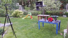 IMG_20160601_213850.jpg365.2 KB · Views: 547
 -
 1 layer, W.jpg105.5 KB · Views: 539
Last edited:
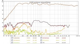
And here's without gating, but with psychoacoustic smoothing:
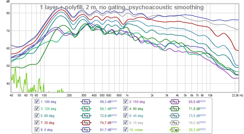
Not sure what happens at low frequencies (below 1 kHz) when comparing gating and without. I'm guessing it's the reflections from the two large flat walls that are 4 and 6 m away that start are removed with the FDW.
/Anton
Not sure what happens at low frequencies (below 1 kHz) when comparing gating and without. I'm guessing it's the reflections from the two large flat walls that are 4 and 6 m away that start are removed with the FDW.
/Anton
Attachments

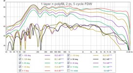
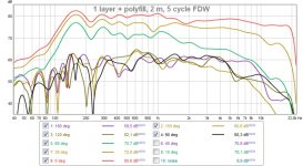
I found out that REW was aligning everything against the impulse reflected off a wall as that had a larger amplitude than the impulse that traveled around the speaker. That's why there was a difference below 1 kHz when comparing woofer response and combined response.
Here is a new figure with FDW with impulse correctly aligned:
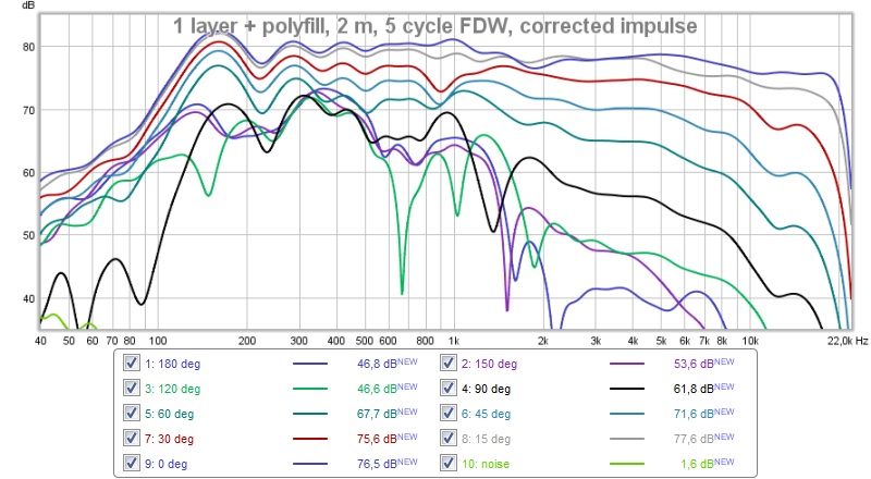
It's still a good result, just a little more reasonable for low frequencies.
/Anton
Here is a new figure with FDW with impulse correctly aligned:
It's still a good result, just a little more reasonable for low frequencies.
/Anton
Attachments
- Home
- Loudspeakers
- Multi-Way
- Synergy attempt without compression driver