Stability problem SymAsym Clone
Hi all,
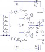
I have prototyped the next SymAsym Clone with high speed devices and now i am running into a stability problem. The configuration is stable with (or without) an input signal applied less than 700 mVolt. ( sinus, triangle, or square wave) With increased input signal the amplifier starts to oscillate. Idle current is set to 100mA.
Does anyone have any other compensation suggestions then already applied?
Thanks,
Piersma
Hi all,
I have prototyped the next SymAsym Clone with high speed devices and now i am running into a stability problem. The configuration is stable with (or without) an input signal applied less than 700 mVolt. ( sinus, triangle, or square wave) With increased input signal the amplifier starts to oscillate. Idle current is set to 100mA.
Does anyone have any other compensation suggestions then already applied?
Thanks,
Piersma
Attachments
pinkmouse said:Michael, the red traces on the top are links, so no power will be going through vias.In fact, all the power and output rails will be beefed up once I have a layout sorted, at the moment they are just placeholders for the real thing whilst I get component positioning organised.
The layout is way too big to fit in the freeware version of Eagle at the moment, and I still have to optimise some cap sizes as well as add all the output network, so I wouldn't be happy to post Eagle files yet. The way I work it would be far too easy for someone to go wrong with what I have done.
Nando, have you played Boogie Wonderland yet? 😉
Not yet !
😀
But I'll play it just because you suggested !
I'm listening to Diana Krall these days, incredible of course ! 😎
Re: Stability problem SymAsym Clone
Piersma, i can't recommend using a predriver stage in symasym, my attempts with triple darlington were unstable.
You might reduce gain by degenerating Q8/9. Also, don't skip REs to Q11/12.
Does it enter real oscillation or just ringing? Can you show scopeshots?
700mv input ? Symasym should clip with values above. You might have a clipping issue. If yes, try clamping diodes between R1/2.
BTW, polarity of c6 needs to be reversed.
Why did you choose CFP output stage?
Mike
Piersma said:Hi all,
I have prototyped the next SymAsym Clone with high speed devices and now i am running into a stability problem. The configuration is stable with (or without) an input signal applied less than 700 mVolt. ( sinus, triangle, or square wave) With increased input signal the amplifier starts to oscillate. Idle current is set to 100mA.
Does anyone have any other compensation suggestions then already applied?
Thanks,
Piersma
Piersma, i can't recommend using a predriver stage in symasym, my attempts with triple darlington were unstable.
You might reduce gain by degenerating Q8/9. Also, don't skip REs to Q11/12.
Does it enter real oscillation or just ringing? Can you show scopeshots?
700mv input ? Symasym should clip with values above. You might have a clipping issue. If yes, try clamping diodes between R1/2.
BTW, polarity of c6 needs to be reversed.
Why did you choose CFP output stage?
Mike
I haven't built this particular variant yet. I previously posted something very similar (then added a link to close its second diff pair) but not exactly this. Making the boards at present. Unfortunately, I have no NJL's yet, so that version may take some time. It's a pity their bce pin configuration didn't stay in the same relative position, with the anode and cathode between, (as in bAcKe) then one board could have met both schemes!
Brian.
Brian.
Try to remove the D3, and use some diodes, as made by Mark Levinson. They used 5-6 diode string, which means about 3V, which is enough for the input transistors, and the diodes makes less noise.
sajti
sajti
"Try to remove the D3, and use some diodes"
Thanks Sajti,
Understood and appreciate any suggested improvements. Others do just this, though.
Difficult to fit six series diodes in the layout.
How about a 2.5V reg +1 diode? Noisier?
Brian.
Thanks Sajti,
Understood and appreciate any suggested improvements. Others do just this, though.
Difficult to fit six series diodes in the layout.
How about a 2.5V reg +1 diode? Noisier?
Brian.
I think that diode string is the best solution. Otherwise Mark Levinson would use different...
In some cheaper amplifier they used diode+resistor with parallel coupled capacitors
Sajti
In some cheaper amplifier they used diode+resistor with parallel coupled capacitors
Sajti
Stability problem
Hello Mike,
I just wanted to try a compoudstage (super-emitter follower) because of its lineairity, thermal stability and its beautiful transfer. (Although a know that the MJLs are very lineair devices) Its not mend to be as a triple darlington. I will investigate if it is really oscillation or a ringing problem but I don't have much time to do that right now. I will do some additional measurents and I will let you know what follows.
For now thanks for your comments.
best regards,
Piersma
Hi Piersma,
Your compound output stage has a lot of gain, doesn't it? Early ETI amplifiers used a similar concept and were famous for oscillating.
-Chris
Your compound output stage has a lot of gain, doesn't it? Early ETI amplifiers used a similar concept and were famous for oscillating.
-Chris
Compound stage
Anatech:
The compoundconfiguration has a high current gain and (almost) no voltage gain and for this reason it doesn't have a dominating pole.
Anatech:
The compoundconfiguration has a high current gain and (almost) no voltage gain and for this reason it doesn't have a dominating pole.
Hi Piersma,
I'm looking at the MJE15030 /MJE15031 devices. Emitter resistance is about 0R5 and the collector load will be a bit less than 47R. Therefore the device has voltage gain unless I'm mistaken. It's just wrapped up in a larger feedback loop.
Am I missing something?
-Chris
I'm looking at the MJE15030 /MJE15031 devices. Emitter resistance is about 0R5 and the collector load will be a bit less than 47R. Therefore the device has voltage gain unless I'm mistaken. It's just wrapped up in a larger feedback loop.
Am I missing something?
-Chris
Tried tp order some PCB´s of http://www.diyaudio.com/forums/attachment.php?s=&postid=1085036&stamp=1166477983
and got the answer:
and got the answer:
How do I fix this?Hi,no readme.txt as per our web template
no soldermask files - note that our process is immersion gold and if no soldermask massive gold deposit on the track will be made which will increase the price of panel x3
Thanks
Olimex
Hi Ryssen,
Easy, no gold. I don't understand why you want to plate with gold anyway. It can only cause soldering problems down the road. Tin plate if you want.
-Chris
Easy, no gold. I don't understand why you want to plate with gold anyway. It can only cause soldering problems down the road. Tin plate if you want.
-Chris
Ok,I wasnt asking for Gold specific but the answer was:note that our process is immersion gold and if no soldermask massive gold deposit on the track will be made which will increase the price of panel x3
Maybee I shoud ask at another company if this one only does gold and it makes it x3 times more expensive..
Other companys to suggest?🙂 Cheap ones..
Maybee I shoud ask at another company if this one only does gold and it makes it x3 times more expensive..
Other companys to suggest?🙂 Cheap ones..
- Status
- Not open for further replies.
- Home
- Amplifiers
- Solid State
- Symasym - the sequel