Since I am mounting one board opposite of the other board I of course connected Q17 (bias) transistor correct on the working board and backwards on the nonworking board. On the nonworking board the Emitter and Base are swapped with where they should be.
I fixed this and I still get the same issue which is a lot of DC and L5 only illuminating if the input is shorted (does not light if input not shorted). Did I blow anything nearby Q17 with my initial short full voltage test, if so which components are recommended to be replaced?
Or is there another undetected problem?
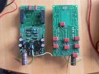
I'm in the home stretch with my pair...& this thread was in need of bumping to make it more accessible. 😉
I've scrounged and reorganized my stash in search of the odd piece for completion. The single 10 ohm R7 will be filled with an Ohmite 10W. A bit of overkill but hey, I had them.
After a trip to the hardware store tomorrow morning for screws and washers I should be ready to heat these up.
I've scrounged and reorganized my stash in search of the odd piece for completion. The single 10 ohm R7 will be filled with an Ohmite 10W. A bit of overkill but hey, I had them.
After a trip to the hardware store tomorrow morning for screws and washers I should be ready to heat these up.
Input FETs
The k170 are reputed to be symmetrical, i.e. Drain and Source can be swapped and the device operates identically. If this really is the case then inserting them back to front should make no difference to performance. QUOTE]
The 2SK170 FET is indeed symetrical, i have tested this device on the Tektronix 571 curvetracer and i can confirm that this FET operates identical when drain and source are swapped.
So there should be no need to rotate the input FETs on AAK's board.
regards,
Piersma
I got about as far on my board assembly as I could. I ran into a wall.  The bag of 2SK170's I set aside were really set aside...out of mind...out of sight. 😕
Short of pulling up the carpet, I have another set on order. I'll resume with matching when they arrive.
The bag of 2SK170's I set aside were really set aside...out of mind...out of sight. 😕Short of pulling up the carpet,
I have another set on order. I'll resume with matching when they arrive.Since I am mounting one board opposite of the other board I of course connected Q17 (bias) transistor correct on the working board and backwards on the nonworking board. On the nonworking board the Emitter and Base are swapped with where they should be.
I fixed this and I still get the same issue which is a lot of DC and L5 only illuminating if the input is shorted (does not light if input not shorted). Did I blow anything nearby Q17 with my initial short full voltage test, if so which components are recommended to be replaced?
Or is there another undetected problem?
OK, I'm turning back to this soon. Any input? Q17 does not appear to be blown up, no terminals measure short circuit w/r to each other.
Hey guys,
I apologize for being away for so long, I've been busy working on other projects among other things. What's up with this thread, it's dead.
How about some updates?
Igreen did you get the amp that was giving you problems working?
How's it going Ed, you must be close to firing up the amps?
Al
I apologize for being away for so long, I've been busy working on other projects among other things. What's up with this thread, it's dead.
How about some updates?
Igreen did you get the amp that was giving you problems working?
How's it going Ed, you must be close to firing up the amps?
Al
How's it going Ed, you must be close to firing up the amps?
I have the wiring above the transformer to clean up. All is ready to heat the boards up this next week.
I also have all of the hardware for the speakers these will power. My target for the system running is early July.
Midwest Audio Fest 2010 - The premier gathering for audio enthusiasts featuring Speaker Design Competition, Auto Sound Challenge and Parts Express Tent Sale
Hi Ed,
That's great to hear that it's all coming together. Looking forward to it.
Are the speakers your design or a kit?
Al
That's great to hear that it's all coming together. Looking forward to it.
Are the speakers your design or a kit?
Al
The speakers have a pedigree, but I guess the same could be said of a mutt...😀
They follow the "Econowave" concept. That allows swapping specific drivers into a 2-way that uses a 12" mid-woofer and a compression driver HF on a horn/waveguide.
I'll use the Eminence Deltalite II 2512, B & C DE250 and a QSC HPR 152i waveguide.
Flex Your PCD Mettle: - Page 10 - Techtalk at Parts-Express.com
These are in a cabinet of less than 2 cf. I will build a MLQW of almost 4 cf.
A passive crossover is provided. I'll use that in the beginning but move on to active.
Testing
I'm using a variac.
I have external fuses.
The board fuses are installed.
I have advanced the variac to 50% power. L3 is not as bright as the other L4 & L5. Upon shut-down, it does glow longer than L4.
I measure dc offset of ~10 mV.
That's where I have stopped.
Looking ahead I must ask about attaching probes to Q22 & Q23 emitters.
As to the location for attachment, I'm scratching my head on this. May I get some direction?
Hi Ed,
For probing Q23 & Q24 refer to the pictures found in post #24. I would replace the fuses with the 100 resistors as described in the Testing Procedure section of the assembly instructions. Make sure though that the bias pot trimmer screw is turned counter-clockwise 25 full turns to ensure the amplifier’s output section is set to it’s minimum bias of about 0ma.
With the variac at 50% it's possible the VAS is not getting enough current resulting in a not so bright L3.
Al
OK,
100 ohm resistors in place. Measured 2.54 & 2.75V across them.
DC offset .009V
At 100% on the variac. L3 is at equal brightness with L4 & L5.
I'm just doing one board at a time.
On to the next step.
100 ohm resistors in place. Measured 2.54 & 2.75V across them.
DC offset .009V
At 100% on the variac. L3 is at equal brightness with L4 & L5.
I'm just doing one board at a time.
On to the next step.
OK, really
It takes more than a few turns to begin seeing bias. Enough so to provoke a feeling of anxiety with the thoughts: "Is something gonna show up? Is it working? Have I hooked it up right?"
So it goes.
The first channel is warmed up,losing bias with slowly increasing temperature. It is in the 55mV range. DC offset is 5mV.
Sweet
The heatsink is horizontal. Not like it will be in use. Close enough at this point to move on the the other channel.
Ed,
Great to hear the first amps is working. Good job! Good luck with the second.
If your heatsink warms up to much you can turn the voltage across Q22&23 down between 25-30mv without sacrificing performance.
Al
Great to hear the first amps is working. Good job! Good luck with the second.
If your heatsink warms up to much you can turn the voltage across Q22&23 down between 25-30mv without sacrificing performance.
Al
Last edited:
I found a happy place for the bias @ 35mV, but will test what happens when I go even lower. It seems that AAK has already measured THD at lower bias settings with no ill effect on THD.
The theoretical optimum in near 40mV, but not a whole lot happens when you go lower. 55mV is definitely too high.
The theoretical optimum in near 40mV, but not a whole lot happens when you go lower. 55mV is definitely too high.
Ed,
Great to hear the first amps is working. Good job! Good luck with the second.
If your heatsink warms up to much you can turn the voltage across Q22&23 down between 25-30mv without sacrificing performance.
Al
- Status
- Not open for further replies.
- Home
- Amplifiers
- Solid State
- SymAsym - "The Sequel", AAK's PCB Builders Thread