There is an alternate PS cap (C3,C4,C5,C6) from Mouser if greater capacitance is desired.
598-SLPX682M063C9P3
This cap is rated 85 degreeC, 6800 uF, 3000 hours, has ~similar ESR & greater Ripple
598-SLPX682M063C9P3
This cap is rated 85 degreeC, 6800 uF, 3000 hours, has ~similar ESR & greater Ripple
Hi all,
I replaced R7 in the BOM with a metal oxide resistor instead of the wirewound type from Vishay.
The Vishay was adding some low level distortion when I connected a specific 4-ohm load to the amplifier output. To make a long story short I figured out that it was coming from the output Zobel Network and the Vishay wirewound was the culprit. I guess it most be a high inductance type.
For those in the states that already bought the parts listed in the BOM check Radio Shack, I'm pretty sure they carry a 1-watt 10ohm metal oxide in their stores. I used a 3-watt but a 1-watt is good enough.
Attached is a new BOM with a 2 watt Xicon Metal Oxide from Mouser added in place of the Vishay wirewound.
Regards,
Al
Attachments
I got around to doing some THD testing on the new amps today, the results were pretty impressive. I did the testing with the rectifiers bypassed using my external power supply (EPS) to beef up the total PS capacitance to 18800uf per rail. First I did the testing at 100 watts into 8ohms, and then 200 watts into to 4 ohms. Without the EPS just using the on-board PS the amp did about 180watts into 4-ohms.
Whether it's into 8 or 4 ohms at full power the amp doesn't blink one bit. Like my other testing the 2nd harmonic is lower than the input, which explains why the overall THD is lower then the input signal. There is a small increase in the 3rd harmonic when driving 4-ohms at full power.
Here are the THD plots.
Al
Attachments
Last edited:
Hi Stanley,
Then verify the current by measuring the voltage across R23 and dividing that value by 681. This should drop the current across R23, and R24 to about 1.65 to 1.75ma dropping the power draw across the SST to about 200mw. If it's off try some different resistor values until you get it within range.
Let me know how it goes.
Regards,
Al
Thanks Al,
I went back to the breadboard testing with different LEDs. I found that Vf for my batch of Red LEDs are slightly lower than my samples of Green LEDs.
At 1.4mA, Vf for Red LED are 1.85V, Vf for Green LED are 1.87V
At 2.8mA, Vf for Red LED are 1.89V, Vf for Green LED are 1.92V.
At 2.8mA, Vf for Sunset Orange LED are 1.719V;
At 7mA, Vf for Sunset Orange LED are 1.787V;
Anyway I have assembled one channel with Red LEDs and waiting for the board to dry. I will keep an eye on the voltage across R23.
Best regards, Stanley
Hi Stanley,
The Vf for the Red LEDs looks good. You probably wont need to adjust R19, but it's good idea to check R23 anyway just in case.
That’s great your done with one amp. Make sure before powering up to double check everything and use the 100 ohm protection resistors in place of the fuses and adjust R36 counter clockwise until you hear a click to set the bias to it's lowest setting.
Good luck!
Al
Last edited:
Build report
I have followed Al's assembly instructions & completed one channel. I will put my 2c:
The PCB is well-made & its layout is good & most pads are of generous sizes. However, there are no wasted space on the amplifier section, if you have not ordered the parts, order the recommended parts as detailed in the BOM.
Follow Al's advices on the soldering guns, I found that my favorite 42W Goot temperature-controlled soldering iron was not hot enough for the power components. I had to use a 80W soldering iron to reflow some joints.
Assembly instruction Step 8 - installing the J1 to J2 Jumper can be tricky. I installed the jumper before I installed R36 trimpot & L3 LED.
The pads for the zener diodes are quite small, you may need a super fine soldering iron tip.
I used the recommended Keystone Faston terminal, (mouser part no: 534-1213), the mating surface tarnished when I overheated them with my 80W iron.
- Stanley
Attachments

Hi,
could you post the design currents passing through the following resistors:
R23 & 24, R31, R21, R22, R19, R33, R32, R10, R11, R16, R37, R8.
ZD3, 6v8 500mW, passes about 1mA. This is only 1.4% of it's power rating.
Does it control/define the cascode voltage adequately @ this low current?
could you post the design currents passing through the following resistors:
R23 & 24, R31, R21, R22, R19, R33, R32, R10, R11, R16, R37, R8.
ZD3, 6v8 500mW, passes about 1mA. This is only 1.4% of it's power rating.
Does it control/define the cascode voltage adequately @ this low current?
Stanley,
That looks good. One thing I forgot to note is the mounting direction for the bias pot R36. The small adjustable screw should be on opposite side of the R36 label near J1. Look at the first pic on post #15 for reference.
Andrew, I'm working on getting you those values.
Al
That looks good. One thing I forgot to note is the mounting direction for the bias pot R36. The small adjustable screw should be on opposite side of the R36 label near J1. Look at the first pic on post #15 for reference.
Andrew, I'm working on getting you those values.
Al
Andrew,
Here are the current values you requested.
R23,R24 -> 1.7ma
R31 -> 1.0ma
R21 -> 3.6ma
R22 -> 2.5ma
R19 -> 4.5ma
R33 -> 8.5ma
R32 -> 2.3ma
R10,R11 -> 21ma
R16 -> 8.5ma
R37,R38 -> 2.5ma
Most of these current readings come from simulations so their not exact but pretty close.
The 1ma across Zd3 is correct.
Al
That's sounds about right. That's works out to about 25mv across each output emitter resistor.
Al
Al
Errors with the latest BOM
Al,
I powered on the SymAsym board today and the two current limiting 100R resistors smoked.
I double-checked & there was no DC short-circuit. I connected the volt meter to one supply rail & it was loaded down to around 3V, so one or more power devices were turned hard on.
When I build the ampflier, I used a hard copy of the latest BOM as a component guide & crossed them out after I installed the component.
I then checked schematics in post #4 and found that Q20 should be 2SA1837 & Q21 should be 2SC4793 and these does not agree with the latest BOM which states that Q20 is a 2SC4793.
I suspected that the schematics is correct.
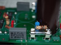
There are no burned tracks. Attached is a photo of the slightly-smoked 100R resitor.
I also noticed that C7 & C8 still have the mouser part: 505-M10.1/250/10 & you mentioned that 505-M10.1/400/10 may be a better choice.
Best regards, Stanley
Al,
I powered on the SymAsym board today and the two current limiting 100R resistors smoked.
I double-checked & there was no DC short-circuit. I connected the volt meter to one supply rail & it was loaded down to around 3V, so one or more power devices were turned hard on.
When I build the ampflier, I used a hard copy of the latest BOM as a component guide & crossed them out after I installed the component.
I then checked schematics in post #4 and found that Q20 should be 2SA1837 & Q21 should be 2SC4793 and these does not agree with the latest BOM which states that Q20 is a 2SC4793.
I suspected that the schematics is correct.
There are no burned tracks. Attached is a photo of the slightly-smoked 100R resitor.
I also noticed that C7 & C8 still have the mouser part: 505-M10.1/250/10 & you mentioned that 505-M10.1/400/10 may be a better choice.
Best regards, Stanley
Attachments
Hi Stanley,
Sorry about the mistake on the BOM. It is correct on the schematic.
From your pic I see the fuse is inserted in the fuse holder, it should not be there just the 100-ohm protection resistors. In the Testing section of Assembly Instruction I wrote not to insert the fuse just the resistor.
To debug first check the drivers and outputs for continuity, basically checking between the base, emitter, and collector for shorts. If there's a short you'll have to replace the part. If you find no shorts then swap the drivers, and without the fuses inserted solder a new set of 100-ohm resistors and try it again to see what happens.
Try that and get back to me.
Al
Stanley,
It's getting late so I'll be hitting the sack. I'll be back tomorrow morning to help you out.
Al
It's getting late so I'll be hitting the sack. I'll be back tomorrow morning to help you out.
Al
Hi Stanley,
Sorry about the mistake on the BOM. It is correct on the schematic.
From your pic I see the fuse is inserted in the fuse holder, it should not be there just the 100-ohm protection resistors. In the Testing section of Assembly Instruction I wrote not to insert the fuse just the resistor.
To debug first check the drivers and outputs for continuity, basically checking between the base, emitter, and collector for shorts. If there's a short you'll have to replace the part. If you find no shorts then swap the drivers, and without the fuses inserted solder a new set of 100-ohm resistors and try it again to see what happens.
Try that and get back to me.
Al
Thanks Al,
There are no shorts in the drivers or OTs, I will swap the drivers to see how it goes.
I soldered the 100R onto the blown fuse so that I can easily remove & reuse them. The setup also works for working 1A fuses as the fuses will go first, then the current-limiting resistors will smoke.
Cheers, Stanley
Is it possible to use matched bf862 (smd) for Q1 en Q2 ?
I get stucked with words like "transconductance". 😱
I get stucked with words like "transconductance". 😱
Problem fixed
Thanks Al,
I had to cut the legs before I could remove Q20 & Q21. The amp worked after I installed new pair of A1837 & C4793.
Current thru the R23 & R24 are around 1.66mA.
I could measured the following current:
R31 = 1.25mA
R21 = 3.46mA
R22 = 2.51mA
R19 = 4.67mA
I adjusted the bias & the DC offset is around -2mV. The heatsink is running a bit hot at 55C (131F), ambient room temperature is 26C.
Best regards, Stanley
Stanley,
It's getting late so I'll be hitting the sack. I'll be back tomorrow morning to help you out.
Al
Thanks Al,
I had to cut the legs before I could remove Q20 & Q21. The amp worked after I installed new pair of A1837 & C4793.
Current thru the R23 & R24 are around 1.66mA.
I could measured the following current:
R31 = 1.25mA
R21 = 3.46mA
R22 = 2.51mA
R19 = 4.67mA
I adjusted the bias & the DC offset is around -2mV. The heatsink is running a bit hot at 55C (131F), ambient room temperature is 26C.
Best regards, Stanley
- Status
- Not open for further replies.
- Home
- Amplifiers
- Solid State
- SymAsym - "The Sequel", AAK's PCB Builders Thread