Hi Andrew,
I updated the PCB with an extra pad for C7 and C8 with a 10mm spacing. I didn't think it would be such a problem.
Your idea would work fine, but be careful not to drill through the top side trace that connects to ground. The trace comes pretty close to where the drill hole would need to be for a 10mm spacing.
Regards
Al
Boards have landed in the UK. 🙂
Many thanks Al, they look great.
cheers
Aidan
PS Do Q22/24 and Q23/25 need matching?
Many thanks Al, they look great.
cheers
Aidan
PS Do Q22/24 and Q23/25 need matching?
Last edited:
Hi Aidan,
Great to hear the boards and parts arrived.
You should match Q22 with Q23, and Q24 and Q25 to closely distribute the power between each pair. I've not tried using an unmatched pair so I can't say for sure how well it would work. You can also use a single pair until you find a matched pair.
Regards,
Al
Hi All
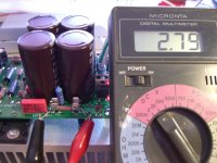
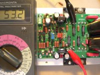
I've added testing procedures to the attached assembly instructions document found in post #1.
Remember if your using the 2SK170s for Q1&Q2 to insert them in the opposite direction then how it's labeled on the board. The flat side of Jfets Q1&Q2 should face inward towards the large PS caps.
I've added a couple pics that should help with the testing.
Regards,
Al
Attachments
Hi Al, could post a picture with physical layout (parts placement and name) it's just more easy to work with since their is a lot of parts with little space...
Marc
Marc
Hi Al, Some picture of "sensible orientation part" would be top to avoid mistake espacialy for non english foreigner as me.
Marc
Marc
Marc,
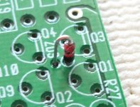
Here's a picture of zener diode Zd3 illustrating the correct orientation. For Zd1, and Zd2 follow the labeling on the board. For LEDs L1-L5 insert the longer of the two leads which is the anode into the pad with the circle labeled around it. Look at the parts placement diagram in post #27, you should clearly the see the circle labeled around the pad for L1-L5.
Al
Attachments
Marc,
That's the way to do it. The objective is to get right the first time, no mistakes.
If someone is not sure about something, don't hesitate to ask, I'm here to help.
Al
That's the way to do it. The objective is to get right the first time, no mistakes.
If someone is not sure about something, don't hesitate to ask, I'm here to help.
Al
Substitute for L3, L4 & L5
Al,
I have almost done with the transistors matching. I checked my parts bin & found that I don't have enough green LEDs. I do have a bunch of 3mm Red LED (standard low-mcd type), their forward voltage drop are very similar to the green LEDs that I have - around 2.02V.
Is the LED type critical for the SymAsym? Can I use standard Red LED for L3, L4 & L5?
- Stanley
Hi Al,
started soldering resistors today. I believe there is a slight error in the BOM -
The BOM has R42 in two places. I think R40 should be one of them, which should be 10R - if I am not mistaken.
cheers
Aidan
🙂
started soldering resistors today. I believe there is a slight error in the BOM -
The BOM has R42 in two places. I think R40 should be one of them, which should be 10R - if I am not mistaken.
cheers
Aidan
🙂
Hi Stanley,
The Red LEDs for L3,L4,L5 with a Vf = 2.02 will work but you will have to readjust R19 to drop the LTP current. According to my simulations using the Red LEDs with a Vf = 2.02v compared to the green LEDs with a Vf = 1.8v will increase the LTP current resulting in about 2.3ma across R23, and R24 which is way to high and will cause Q7,Q8,Q9,Q12, and Q21 to overheat drawing over 300mw of power each.
So here's what I suggest you do, for R19 replace the 261-ohm resistor with about a 320-ohm resistor. Then verify the current by measuring the voltage across R23 and dividing that value by 681. This should drop the current across R23, and R24 to about 1.65 to 1.75ma dropping the power draw across the SST to about 200mw. If it's off try some different resistor values until you get it within range.
Let me know how it goes.
Regards,
Al
Al,
I noticed that the value of R5 and R6 on the BOM should also needs correction. It should be 10K, right? Correct me if I'm wrong.
R5,R6 Metal Film 4.7K 2.0 watts 283-10K-RC
I noticed that the value of R5 and R6 on the BOM should also needs correction. It should be 10K, right? Correct me if I'm wrong.
R5,R6 Metal Film 4.7K 2.0 watts 283-10K-RC
May I sub some MUR820 (8 A) for the MUR1520 called out in the bom?
Is 8 A cutting it too close?
Also, is the output pair MJW1302A/MJW3281A OK to substitute?
Is 8 A cutting it too close?
Also, is the output pair MJW1302A/MJW3281A OK to substitute?
Last edited:
Hi Ed,
The MUR820 is cutting it pretty close, especially if your using 50V rails. If you do use them try not to do any heavy testing at high outputs levels into a resistive load. For music it should be fine as long you don't blast the amps for long periods. For casual listening no problem.
I've tested the MJW1302A/MJW3281A, they worked fine.
Regards,
Al
Last edited:
- Status
- Not open for further replies.
- Home
- Amplifiers
- Solid State
- SymAsym - "The Sequel", AAK's PCB Builders Thread