Hi Al,
just realized the diagram you gave for connection of a PS if not using the onboard diodes
Post 31
shows the wrong polarity. The description you give in the text is correct, but the schematic has the wrong polarity for connection of outboard unregulated DC. Just FWIW in case someone uses post 31 without checking!
A wrong connection here would be very dangerous (immediate explosion of large caps).
Thanks MBK for pointing it out. I don't know how I missed that one, but boy am I glad you did. Many thanks!
Can the moderators please replace the diagram in post #31 with this one.
Thanks,
Al
Edit: Hi Al, done as you requested - The moderating team 😉
Can the moderators please replace the diagram in post #31 with this one.
Thanks,
Al
Edit: Hi Al, done as you requested - The moderating team 😉
Attachments

Another pair almost completed.
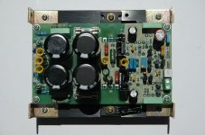
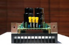
AAK boards stuffed and mounted.

Parts chosen and why-
Q1,Q2-2SD786 they're very low noise and I have some left. Snag is they prefer low impedance input. But I plan to fit a pre or buffer stage anyway.
U5,U6-2SC4793/SA1837 most recommended drivers and they're cheap as chips at the local RS.
U3,U4-2SC2922/SA1216 cost only slightly more than 5200/1943 here. These Sankens are highly thought of output BJTs. Those in the know say they are very linear and fast. I'm sold because my Sanken fitted early NAP140 sound sweeter than later TO-3 fitted NAP140s.
Transformer - 2x new Nuvotem Talema 160VA 0-25,0 -25 encapsulated toroid. Busted the bank on these. Irish heavy iron made in Czech.
Filter caps - Black and gold just marked 'Audio' but surplus store guy pointed out bracketed 'M' means Matsushita i.e. Panasonic
Input resistor - Riken Ohm. Only two needed and they are in the signal welcoming committee. So I splurged. A total of US$2.00.
Input caps - Solen MKP. Ditto above but US$5.00.
A sprinkling of Welwyn RC55y resistors on positions I deem strategic.
Feedback elyt - Elna Tonerex. Silmics too big. Should have gone with Oscons?
Rail decoupling elyt - Elna Silmics
Heatsinks - surplus store abt US$1.50 ea.
Actually the thermal paste alone cost five times more than the sinks but have been amortised over a long period of PC overclocking mods.
Question is.
Will these suckers run?
AAK boards stuffed and mounted.
Parts chosen and why-
Q1,Q2-2SD786 they're very low noise and I have some left. Snag is they prefer low impedance input. But I plan to fit a pre or buffer stage anyway.
U5,U6-2SC4793/SA1837 most recommended drivers and they're cheap as chips at the local RS.
U3,U4-2SC2922/SA1216 cost only slightly more than 5200/1943 here. These Sankens are highly thought of output BJTs. Those in the know say they are very linear and fast. I'm sold because my Sanken fitted early NAP140 sound sweeter than later TO-3 fitted NAP140s.
Transformer - 2x new Nuvotem Talema 160VA 0-25,0 -25 encapsulated toroid. Busted the bank on these. Irish heavy iron made in Czech.
Filter caps - Black and gold just marked 'Audio' but surplus store guy pointed out bracketed 'M' means Matsushita i.e. Panasonic
Input resistor - Riken Ohm. Only two needed and they are in the signal welcoming committee. So I splurged. A total of US$2.00.
Input caps - Solen MKP. Ditto above but US$5.00.
A sprinkling of Welwyn RC55y resistors on positions I deem strategic.
Feedback elyt - Elna Tonerex. Silmics too big. Should have gone with Oscons?
Rail decoupling elyt - Elna Silmics
Heatsinks - surplus store abt US$1.50 ea.
Actually the thermal paste alone cost five times more than the sinks but have been amortised over a long period of PC overclocking mods.
Question is.
Will these suckers run?
Al,
pure luck, as I was finally stuffing my first board I double checked everything...
Cromodora,
hilarious, we must be patronizing the same establishments... these heatsinks look awfully familiar. Let me guess, they have some M2.5 threads in them, and two square recesses in the back? Industrial automation, SLT 3rd floor I say. This one was the only heatsink I found including from RS that was the perfect match to the PCB requirements.
I also bought a lot from RS so I would only have one overseas shipment (from Digikey), so I substituted parts liberally as well. I got some Elna 3300 uF from surplus, so I mate 3300 with 5600 uF rather than having 2x 4800 uF. RS took a long time for some backordered parts so I only did one board so far, today, complete save for the output pair. My XF are the 225 VA Nuvotem-Talema, unshielded, each will power two channels with external standard (surplus) 25A bridge.
pure luck, as I was finally stuffing my first board I double checked everything...
Cromodora,
hilarious, we must be patronizing the same establishments... these heatsinks look awfully familiar. Let me guess, they have some M2.5 threads in them, and two square recesses in the back?
Industrial automation, SLT 3rd floor I say. This one was the only heatsink I found including from RS that was the perfect match to the PCB requirements.I also bought a lot from RS so I would only have one overseas shipment (from Digikey), so I substituted parts liberally as well. I got some Elna 3300 uF from surplus, so I mate 3300 with 5600 uF rather than having 2x 4800 uF. RS took a long time for some backordered parts so I only did one board so far, today, complete save for the output pair. My XF are the 225 VA Nuvotem-Talema, unshielded, each will power two channels with external standard (surplus) 25A bridge.
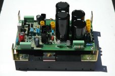
Full aerial. One trouble I had was that the TO-220 heat sinks for the drivers leave too little clearance to adjacent parts and to the connectors. All else went failry OK. Now I have to unmount my existing transformers from my main system for a first test. Unfortunately I have no scope so I'll have to fly blind w.r.t. oscillations, except if they're so massive that the Zobel is melting...
Attachments
Beautifully neat!
Excellent work MBK. And good taste in heatsinks I must say.
I need to find sinks for the drivers too. Tight fit there.
Are those Rubycons power decoupling and Cerafine for feedback?
Yup lots of goodies at Kaichin Industrial side but the lady there a bit surly.
Eyeing the 500va with 110 and 24v secondaries toroids there. Just the thing for a future Geddon clone/prefix psu in one box.
Thanks...
I think that's a SLT thing 🙄
The feedback C is Elna, yes, from RS, and the power decoupling small elcaps are Nichicons.
Well, I did fire it up today but while it didn't blow entirely, I do get too much bias. Depending on the setting of R22 I can vary it between , ahem, 1.5A and 2.5 A only, obviously there is at least an order of magnitude of a problem here.
The rails drop to ca. 33V at this bias btw, from 38V or so which they're supposed to be. No DC offset at the output (2.3 mV actually) so I suppose no active devices near the output blew outright / mounted wrong. Also, the values around T1 seem to be correct. Suppose I'm, up for a long session of bug fixing...
Any ideas for first candidates of what may be wrong?
but the lady there a bit surly
I think that's a SLT thing 🙄
The feedback C is Elna, yes, from RS, and the power decoupling small elcaps are Nichicons.
Well, I did fire it up today but while it didn't blow entirely, I do get too much bias. Depending on the setting of R22 I can vary it between , ahem, 1.5A and 2.5 A only, obviously there is at least an order of magnitude of a problem here.
The rails drop to ca. 33V at this bias btw, from 38V or so which they're supposed to be. No DC offset at the output (2.3 mV actually) so I suppose no active devices near the output blew outright / mounted wrong. Also, the values around T1 seem to be correct. Suppose I'm, up for a long session of bug fixing...
Any ideas for first candidates of what may be wrong?
Aw ne'rmind. Looks like I switched base for emitter in T1, obviously T1 because it's the only one where I'd actually needed a brain to mount it. I only spent about 10 minutes triple checking that I had the pin order down correctly when I stuffed the board. 🙄
Hi Al,
I used your BOM with small variations 😉 . For instance re: bias network, for R22 I used 200 Ohms to get a wider range of bias settings. I bought almost all Digikey items as of your BOM from there, but didn't want to shell out another $30 shipping for Mouser, so I got the Mouser stuff locally from RS, as far as I could with similar specs.
I measured bias by taking VDC over R27 or R28 and calculating. It really was that high, the heatsink got all toasty within seconds. I never left it on for more than a few seconds actually.
Now I fixed T1's connections (actually replaced T1 with a new BD139). Now the bias is at 25 mA (5 mV across R27), which seems to be the highest bias I can get. Heatsinks barely warm at all after 10 minutes. What bugs me now is the DC offset (across a 6 Ohm dummy load, with shorted inputs): it is low, but wanders between 0.2 and 2.5 mV in a ca. 2 sec. rhythm. As far as I can tell though the Zobel is not getting warm. I used Mike's recommended R//L filter as well (soldered inline speaker cable at the connector's , board side) and this one too is not getting warm. Vcc now steady at +-37.8V.
Hi MBK,
That's sounds more like it. The bias is a little to low at 5mv, but the DC offset is where it should be. To increase the bias you'll need to drop R24 (316 ohms) to about 220 ohms and you should be all set. Make sure you turn R22 to it's lowest bias setting prior to powering up then set the bias to about 20 to 25mv across R27.
Al
Al,
thanks, will do. How about the unstable DC offset? A result of the low bias? Or the drivers themselves? (I wiggled one quite a bit after soldering, to get better heat sink clearance, might have damaged it?)
Voltages across R8 / R9, R27 and R28, and between C and E of T1, are all rock stable.
thanks, will do. How about the unstable DC offset? A result of the low bias? Or the drivers themselves? (I wiggled one quite a bit after soldering, to get better heat sink clearance, might have damaged it?)
Voltages across R8 / R9, R27 and R28, and between C and E of T1, are all rock stable.
Hi MBK,
DC offset may drift around a little. Often this is normal, don't worry about it. It's most probably thermal in nature.
-Chris
DC offset may drift around a little. Often this is normal, don't worry about it. It's most probably thermal in nature.
-Chris
Hi Chris,
couldn't resist and checked. You are so right. I had a fan on, on sweep mode, when I reported my values. With fan off and not a movement in the workshop, DC offset is 0.0-0.2 mV. So much as waving a hand at the drivers/thermal transistor, shoots it up to 1-2.5 mV, pretty much instantaneously.
The moving fan did it.
MBK,
You did a great job of matching up the transistors to get such low DC offset. Now, how about supplying some music to the input to see what happens. The suspense is killing me.
Al
You did a great job of matching up the transistors to get such low DC offset. Now, how about supplying some music to the input to see what happens. The suspense is killing me.
Al
Thanks, the matching took me quite some time indeed...
As for listening for meaningful results I'd have to do the 2nd channel first... I thought for once instead of just cobbling stuff together and throwing it into the system this time I'll be thorough!
As for listening for meaningful results I'd have to do the 2nd channel first... I thought for once instead of just cobbling stuff together and throwing it into the system this time I'll be thorough!
- Home
- Amplifiers
- Solid State
- Symasym 5.3 "AAK model" builder's thread