To explain this a bit better: I actually don't have any "conventional" speaker around to test it with music on fullrange mono. I am building a total of 6 channels for my mains, a 3-way OB with active x-o. replacing just one channel would mean testing over a narrow frequency band and in mono... I think the first meaningful listening test I can do is to replace both tweeter channels.
Don't worry I am just as curious!
Don't worry I am just as curious!
Houston, we have a...
Tried firing up today.
Only one trafo connected to test one amp board a time.
All I got was smoke from R32. Shut it down and checked board. Only R32 was burned.
It happened again with the other board.
Help with diagnosis please.
Tried firing up today.
Only one trafo connected to test one amp board a time.
All I got was smoke from R32. Shut it down and checked board. Only R32 was burned.
It happened again with the other board.
Help with diagnosis please.
Sorry to hear... And the fuse did not blow? maybe less than 5A did it. If it happened on 2 boards then it wouldn't be an isolated solder bridge, so maybe it's a systemic mounting mistake. For instance C9 in reverse polarity - the elcap becoming DC conductive and shunting to ground. Normally they explode while doing this but maybe you were quick on turning off or R22's obliteration prevented further reverse bias.
Well on mine I changed R24 to 180 Ohms which I had on hand and tried a high 150 mA bias (30 mV across R27/28). Bias quite stable, the heatsink gets to ca. 45-50 degrees Celsius or so (I can still hold the hand on it indefinitely but it is certainly feeling hot). This sits well with estimations from thermal resistance. Unfortunately the Toshiba's data sheet does not give a thermal resistance for package to junction so I can't calculate the likely junction temperature. Any estimates whether a 45 degree heatsink is safe idea in the long run?
Well on mine I changed R24 to 180 Ohms which I had on hand and tried a high 150 mA bias (30 mV across R27/28). Bias quite stable, the heatsink gets to ca. 45-50 degrees Celsius or so (I can still hold the hand on it indefinitely but it is certainly feeling hot). This sits well with estimations from thermal resistance. Unfortunately the Toshiba's data sheet does not give a thermal resistance for package to junction so I can't calculate the likely junction temperature. Any estimates whether a 45 degree heatsink is safe idea in the long run?
Had the same problem.
Mine was due to using a thermal interface material that was electrically conductive. I'd definitely use the NTE TP0010 Thermo-Pad called for in Al's BOM. And I wouldn't overtighten the screws affixing the output transistors to the sink.
George
Mine was due to using a thermal interface material that was electrically conductive. I'd definitely use the NTE TP0010 Thermo-Pad called for in Al's BOM. And I wouldn't overtighten the screws affixing the output transistors to the sink.
George
That could be it. I'll try remounting the heatsinks.
I have some mica washers but they are not in MT200 size (where to find them?).
Maybe apply more paste and not tighten up too much squeezing it out else whole heatsink also becomes collector of the output bjts.
thanks all.
I have some mica washers but they are not in MT200 size (where to find them?).
Maybe apply more paste and not tighten up too much squeezing it out else whole heatsink also becomes collector of the output bjts.
thanks all.
Definitely needs an insulating washer, not just paste!
FWIW I used SilPad 900S, from Digikey at the price of gold roughly (on a per weight basis this might actually be true haha. You can buy a whole transistor for that money). RS did not have appropriate material in the size required.
Advantage of the SilPad is no fuss during mounting, no paste, no breaking. Disadvantage is slightly higher thermal resistance wrt mica, and degeneration over time means it must be replaced if dismounted after prolonged use.
But if I might say so the mounting process was a true pleasure compared to micas...
Hi MBK,
I prefer and still use mica over those plastic composites. What can I say? Sometimes the old ways are still the best.
You should be fine though. The SymAsym is a well behaved little amplifier.
-Chris
I prefer and still use mica over those plastic composites. What can I say? Sometimes the old ways are still the best.
You should be fine though. The SymAsym is a well behaved little amplifier.
-Chris
Have you tried the range of bias you can adjust to with this resistor (R24)?Well on mine I changed R24 to 180 Ohms which I had on hand and tried a high 150 mA bias (30 mV across R27/28).
According to my classA.xls sheet,that biaspiont the heat on the sinks would be 10,1 watts,and leave 0,3W classA to speakers,I would like a litte more,if its possible.
10 W, yes, that's also what I calculate. Initially I wanted to get 1 W RMS of class A into 8 Ohms but that would require 0.5 A bias if I am not mistaken and my heatsinks just can't take that. In fact likely will settle to 5 W dissipation, that is 75mA bias, which gives me a kid friendly heatsink temperature. 🙂
My R24=180R can yield a maximum of 0.9 A bias, so there is definitely room at the top if your heatsinks are up to it.
My R24=180R can yield a maximum of 0.9 A bias, so there is definitely room at the top if your heatsinks are up to it.
Now all hooked up...
Replacing the blown resistors was quite an ordeal since they are right above the output bjt. Hope I do not have to unmount the heatsinks again. Messy business with the thermal paste and aligning screws to holes. Good news was I had a few large TO3 mica pads in hand which I cut to size to fit the Sankens.
Power on and..
this time no smoke and no smell from boards and no heat from heatsink.
Got a steady +- 37.6V (25v trafo) between r31/r32 and ground.
Can someone help walk me through how to set bias?
Hi cromodora,
Do you have a distortion analyzer and a 'scope, along with a low distortion audio generator? A 4R load would help here as well.
-Chris
Do you have a distortion analyzer and a 'scope, along with a low distortion audio generator? A 4R load would help here as well.
-Chris
Thanks Chris,
but I only have a DMM I'm afraid. Can rummage thru my parts bin for a high power 4 or 6 ohm resistor though. Will that do?
but I only have a DMM I'm afraid. Can rummage thru my parts bin for a high power 4 or 6 ohm resistor though. Will that do?
Hi cromodora,
-Chris
Nope. Don't worry about my method. Look on the web site and set your bias depending on the outputs you used. Click on the "www" button under MikeB's name at the bottom of his post.but I only have a DMM I'm afraid. Can rummage thru my parts bin for a high power 4 or 6 ohm resistor though. Will that do?
-Chris
Hi Cromodora,
the bias is set by measuring voltage across R27 or R28, and calculating bias current from that voltage using I=U/R. Since R27=R28=0.2 Ohms this means Biascurrent = Voltage R27 / 0.2
To increase accuracy you can also measure across both R27 and R28 (clip DMM probes to those ends of R27 and R28 closest to the output transistors). In that case you divide by 0.4 Ohms.
The actual setting is by adjusting R22: watch the measured voltage while you turn the adjustment screw. Start with the highest value of R22 (100 Ohms using AAK's BOM), that is the lowest bias, likely zero.
Numerical example: I settled on 75 mA bias, that is 0.075 A, corresponding to 30 mV = 0.03 V, across *both* emitter resistors R27 and R28: 0.03/0.4=0.075.
Now for my own troubles...
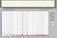
I finished my second channel. THis time DC offset is ca. 9 mV. AC noise is unmeasurable, and can not be heard on a typical 87 dB efficient driver. Picture of noise and HD spectrum at 440 Hz, 16V RMS into no load, is attached, with comparison to the loopback values of my USB mobile pre that I use for measurement. Excellent figures I'd say.
I also drove those 16 V RMS into a 6 Ohms dummy load (ca. -3 dB of full power, or 40 W) for a power test, this gets the heatsink uncomfortably warm, I presume with that output there is about equal dissipation on the amp side and this heatsink is I believe about 1.4 C/W so no surprise here.
Unfortunately I could not yet measure distortion under load. The modile pre / laptop combo has massive ground loops if plugged into power, for once (it is earthed and so is the amp psu). But even running the laptop on batteries, as soon as I attempt to measure voltage across the dummy load I burn a PCB fuse, instantly. There must be the mother of all ground loops forming, between what is in effect the power ground, looping to the preamp input and from there right back to the pre output that delivers the signal, with positive feedback.
I actually built a -32 dB voltage divider probe to measure power output, this may or may not be the issue, because this same connection works fine with no load. But as soon as there is a load on the amp (and thus a power current sensed by the probe going to the pre), the fuse blows. I tried all combinations, after 3 fuses I think I'll have to build a differential probe since the pre has balanced inputs anyway (which I had grounded by using a 2 pole phono plug as input for the voltage divider probe). Or maybe just leave the probe greound disconnected altogether, I forgot to try that...
the bias is set by measuring voltage across R27 or R28, and calculating bias current from that voltage using I=U/R. Since R27=R28=0.2 Ohms this means Biascurrent = Voltage R27 / 0.2
To increase accuracy you can also measure across both R27 and R28 (clip DMM probes to those ends of R27 and R28 closest to the output transistors). In that case you divide by 0.4 Ohms.
The actual setting is by adjusting R22: watch the measured voltage while you turn the adjustment screw. Start with the highest value of R22 (100 Ohms using AAK's BOM), that is the lowest bias, likely zero.
Numerical example: I settled on 75 mA bias, that is 0.075 A, corresponding to 30 mV = 0.03 V, across *both* emitter resistors R27 and R28: 0.03/0.4=0.075.
Now for my own troubles...
I finished my second channel. THis time DC offset is ca. 9 mV. AC noise is unmeasurable, and can not be heard on a typical 87 dB efficient driver. Picture of noise and HD spectrum at 440 Hz, 16V RMS into no load, is attached, with comparison to the loopback values of my USB mobile pre that I use for measurement. Excellent figures I'd say.
I also drove those 16 V RMS into a 6 Ohms dummy load (ca. -3 dB of full power, or 40 W) for a power test, this gets the heatsink uncomfortably warm, I presume with that output there is about equal dissipation on the amp side and this heatsink is I believe about 1.4 C/W so no surprise here.
Unfortunately I could not yet measure distortion under load. The modile pre / laptop combo has massive ground loops if plugged into power, for once (it is earthed and so is the amp psu). But even running the laptop on batteries, as soon as I attempt to measure voltage across the dummy load I burn a PCB fuse, instantly. There must be the mother of all ground loops forming, between what is in effect the power ground, looping to the preamp input and from there right back to the pre output that delivers the signal, with positive feedback.
I actually built a -32 dB voltage divider probe to measure power output, this may or may not be the issue, because this same connection works fine with no load. But as soon as there is a load on the amp (and thus a power current sensed by the probe going to the pre), the fuse blows. I tried all combinations, after 3 fuses I think I'll have to build a differential probe since the pre has balanced inputs anyway (which I had grounded by using a 2 pole phono plug as input for the voltage divider probe). Or maybe just leave the probe greound disconnected altogether, I forgot to try that...
Attachments
Thanks for the reply MBK. Just one more question...
In order to adjust the bias should the input be fed a signal or shorted? Also should the output be loaded with a resistor?
In order to adjust the bias should the input be fed a signal or shorted? Also should the output be loaded with a resistor?
Shorting the inputs is always a good idea to stabilize the input side. I used a load resistor as well but this shouldn't have an influence on the setting.
Hi cromodora,
To explain further, bias is always set with no load (speakers disconnected) and no input to the amplifier. Some amplifiers can take a while to settle into the new setting.
-Chris
To explain further, bias is always set with no load (speakers disconnected) and no input to the amplifier. Some amplifiers can take a while to settle into the new setting.
-Chris
Good to know, I thought shorted inputs and a load were always advised.
I am having a terrible time trying to establish a basic clean bill of health for mine in the meanwhile... All I want is basic THD under load and some assurance of no oscillation... But... No scope, so I can only do soundcard based HD measurements, and I suspect my outboard pre/soundcard (M-Audio mobile pre) is having a creeping short, because I get odd and inconsistent readings whenever I try to measure output with a load while sending a signal from the same soundcard. I don't blow fuses anymore on the amp, but there does seem to be a level dependent bleed through between inputs and outputs - RTA shows a soundcard input signal whenever there is a soundcard output signal, even when the soundcard input is open or shorted... and signs of severe clipping even on the loopback signal at levels way below full out or input. Ah well, just ranting, I'll have to debug this and it's a pain.
On the bright side, the PCB wiring for a single transformer with rectification driving two channels with PSU section sans diodes (Al's diagram a few posts back) does its job: no additional noise and no hum when running a second PCB from a single raw DC supply.
HI MBK,
Yes, sound cards are a rough way to troubleshoot. Ground loops and other issues always get in the way.
No way you can borrow a scope for now?
-Chris
Yes, sound cards are a rough way to troubleshoot. Ground loops and other issues always get in the way.
No way you can borrow a scope for now?
I would only maintain a load with a tube based amplifier, or one that uses a transformer output.Good to know, I thought shorted inputs and a load were always advised.
-Chris
No luck here... to double check whether it's the soundcard or the amp after all I used my desktop soundcard. This time I got consistent readings but oddly high HD, highest was 3rd at 0.15% (0.1W) to 0.38% (10W), plus a lot of PSU noise of course. The loopback measurement was clean though. Well, I thought I try no load again, which at first gave me the beautiful reading a few posts above. My voltage divider was soldered to the load so I turned down the output to 0.7V and connected the soundcard input directly to the speaker leads with no load. Of course I turned it off first. And on again with no signal. But. There *is* a slight turn on thump, maybe 2, 3 V on the DMM.
And that fried the PC. Not just the soundcard input, that would have been too easy, it did an instant protective shutdown and that was that. I've done these measurements dozens of times these past days, but always on the laptop with the USB breakout box and no ill effects. I conclude that M-Audio did something right after all (overload protection haha).
So. I will wait and ponder for a while now, at least as long as the PC is in the shop. I don't have the guts right now to try and fry the laptop too.
In any case... opinions on that high 3rd harmonic and following spray of harmonics? Could it possibly be shaky contacts to the probe (using crocodile clips to connect to the power resistor's terminal that serves as load)? I figure a faulty active device would rather produce even order harmonics? Amp runs cool with no or low input and I found no solder bridges.
Sigh.
- Home
- Amplifiers
- Solid State
- Symasym 5.3 "AAK model" builder's thread