Here's another pic from the top side.
http://www.diyaudio.com/forums/attachment.php?s=&postid=1084932&stamp=1166471914
http://www.diyaudio.com/forums/attachment.php?s=&postid=1084932&stamp=1166471914
I decided to try MJW0302/MJW0281.Did you get any response to your question?
I´ll do that.You'll need to mount T1 (BD139) onto one of the output transistors (U3,U4) to prevent thermal run away.
Are there any sonical benefits in striping the big e-lyts together?
I´ve noticed when I hold them they touch together.
Hi Ryssen,
There are no sonic benefits in holding the AC caps together. I just thought it looked neater.
BTW, your doing a great job. One thing though, I'd recommend extending the output transistors beyond the edge of the board by at least 12mm. This will make mounting T1 and the OT to the heatsink much easier
Just like the pic shows.
http://www.diyaudio.com/forums/attachment.php?s=&postid=1084932&stamp=1166471914
Regards,
Al
Sorry,it´s not possible with my heatsinks.
I bought this heatsinks for the original Symasym PCB´s,and the output transistors on them are soldered in a 90 degre angle.So with this PCB´s I have 2 options:
1:First mount the outputtransistors to the heatsink,then the PCB and solder the transistors.
2: Drill 2 holes in the PCB for the transistors and solder them,then mount the PCB (and transistors) to the heatsink.
Either way will work.
Unless there is a 3:de alternative?🙂
An externally hosted image should be here but it was not working when we last tested it.
I bought this heatsinks for the original Symasym PCB´s,and the output transistors on them are soldered in a 90 degre angle.So with this PCB´s I have 2 options:
1:First mount the outputtransistors to the heatsink,then the PCB and solder the transistors.
2: Drill 2 holes in the PCB for the transistors and solder them,then mount the PCB (and transistors) to the heatsink.
Either way will work.
Unless there is a 3:de alternative?🙂
Chassis ground (DUMMY ALERT!)
Hi, Al:
Is your board designed to be connected to the star ground with a lead from the central "GND" tap?
Thanks.
George
Hi, Al:
Is your board designed to be connected to the star ground with a lead from the central "GND" tap?
Thanks.
George
Ryssen,
Both your options will work. Just a couple notes.
For option 1:
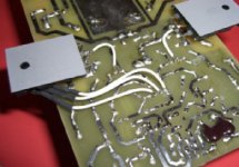
You first mount the OT including TI to the heatsinks. Then connect T1 to the PCB from underneath using wires like illustrated in the picture below. Then align the PCB with OT leads and solder.
For option 2:
Be careful not drill through the power traces. If you have no choice just reconnect them.
Al
Both your options will work. Just a couple notes.
For option 1:
You first mount the OT including TI to the heatsinks. Then connect T1 to the PCB from underneath using wires like illustrated in the picture below. Then align the PCB with OT leads and solder.
For option 2:
Be careful not drill through the power traces. If you have no choice just reconnect them.
Al
Attachments
Hi George,
There is no need for an external star ground since the PS is on the board. That's all taken care and one of the benefits of having the PS and amplifier on the same PCB. Just connect the transformer two AC and CT wires to the board as labeled. Your speaker ground is connected to the GND label. And audio ground to the Gnd where TB1 would go.
Do you plan on using an external PS?
Regards,
Al
Thanks, Al.
I thought that was the case, so I didn't configure my star ground (i.e., chassis "safety" ground, transformer RFI screen drain and AC wiring shield drain) to be easily accessible from the board. However, when I saw that Ryssen had two leads coming from his board's GND tap, I thought "Oh, s***, I better check with Al."
Nice not to have to redo the chassis. Compared to the PITA factor of designing and building small, mirror-imaged monobloc chassis with hand tools, populating the boards is going to be a pleasure (except for my Rube Goldberg solution for mounting oversize BG filtering caps). I'm glad I'm so old these amps can be used at my wake. While an enjoyable challenge, I wouldn't want to allot additional listening time to component construction.
George
Hmm,thats what i was thinking with one of the black leads,one goes to speaker,and one to the chassis "safety" ground,maybee with a resistor (10 ohm).Or should I not connect it that way?when I saw that Ryssen had two leads coming from his board's GND tap, I thought "Oh, s***, I better check with Al."
Hi Ryseen,
I would not connect the amplifier ground to the enclosure chassis. You can try it for safety reason to see what happens, but most likely it will create a ground loop between both channels producing hum. For safety, connect the mains earth ground to the chassis instead.
Regards,
Al
I would not connect the amplifier ground to the enclosure chassis. You can try it for safety reason to see what happens, but most likely it will create a ground loop between both channels producing hum. For safety, connect the mains earth ground to the chassis instead.
Regards,
Al
Anybody have any...
I've run into a wall populating my boards. Somehow, I failed to order the following caps, and they now seem to be unavailable, except in large quantities. I'd gladly send you my first born for some.
WIMA 4.7uF, 50V (MKS2-4.7/50/10)
WIMA 0.1uF, 250V (M10.1/250/10)
I've run into a wall populating my boards. Somehow, I failed to order the following caps, and they now seem to be unavailable, except in large quantities. I'd gladly send you my first born for some.
WIMA 4.7uF, 50V (MKS2-4.7/50/10)
WIMA 0.1uF, 250V (M10.1/250/10)
Anybody have any...
I've run into a wall populating my boards. Somehow, I failed to order the following caps, and they now seem to be unavailable, except in large quantities. I'd gladly send you my first born for some.
WIMA 4.7uF, 50V (MKS2-4.7/50/10)
WIMA 0.1uF, 250V (M10.1/250/10)
Thanks.
George
I've run into a wall populating my boards. Somehow, I failed to order the following caps, and they now seem to be unavailable, except in large quantities. I'd gladly send you my first born for some.
WIMA 4.7uF, 50V (MKS2-4.7/50/10)
WIMA 0.1uF, 250V (M10.1/250/10)
Thanks.
George

Thanks, Ryssen, I'll check.
But I'd still like to have them installed, just in case I change sources.
George
But I'd still like to have them installed, just in case I change sources.
George
Just do a search on "capacistors" 0,1uF 250v.I dont think that as high as 250v i needed,but..and the prefered "leg distance".That´s what I did and got a long list of them..🙂
Found an alternate.
Found this morning that Mouser has in stock the 5% version of the WIMA 0.1uF, 250V: MKP10-.1/250/5 PCM15. A little bit more expensive, but available.
Still looking for the 4.7 uF WIMA. Do any European members know of a site that has English pages?
Thanks.
George
Found this morning that Mouser has in stock the 5% version of the WIMA 0.1uF, 250V: MKP10-.1/250/5 PCM15. A little bit more expensive, but available.
Still looking for the 4.7 uF WIMA. Do any European members know of a site that has English pages?
Thanks.
George

Hi Ryssen,
No problem with the 0.1uF caps here. I have them on hand. It's the 4u7 values. I have not been able to find them in North America. Not in 5mm lead spacing.
-Chris
No problem with the 0.1uF caps here. I have them on hand. It's the 4u7 values. I have not been able to find them in North America. Not in 5mm lead spacing.
-Chris
My view on caps...
I found the four 0.1 uF 250v red Wimas to be a tight fit on the board.
Two extend beyond the edge of the board while the other two are eating into the smoothing caps' parking space.
For input decoupling, I wouldn't worry about non-availability of 4.7uF Wimas. Why not try some real big *** audiophile but not too pricey metallised polypropylenes like the Solen MKPs or even Mundorfs. Connect one end to the board and the other straight to your input connector. I think the Symasym deserve them and input signal caps are where you get best bang for the buck.
- Home
- Amplifiers
- Solid State
- Symasym 5.3 "AAK model" builder's thread